Basic Elements of User Interface
The User Interface of the Tool is a rich-client application. It is simple and easy to use.
Overview of User Interface
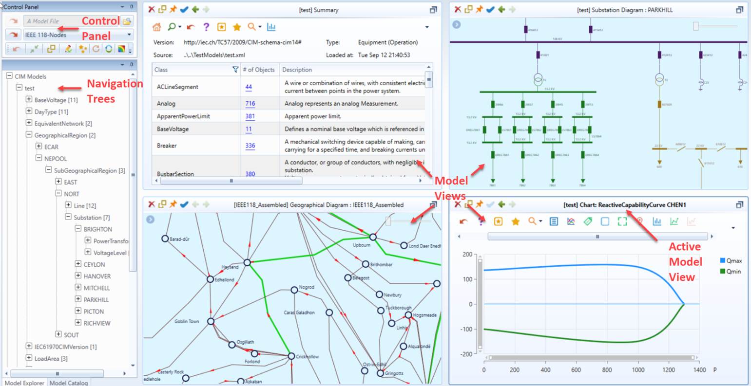
The User Interface (UI) of the Tool contains mainly three major components, as summarized and illustrated below:
- Control Panel: Providing quick access to some of the application-wide commands, such as loading/unloading models, toggling between read-only and editing modes, etc.
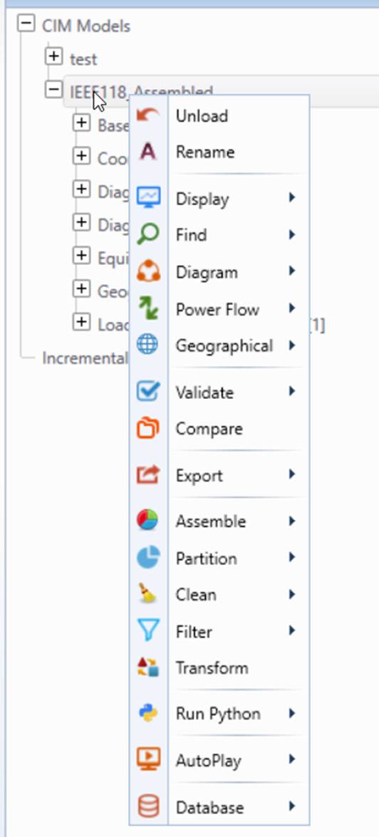
- Navigation trees: Organizing the loaded models into various hierarchies in support of model browsing and many other modeling tasks. Navigation trees provide an overview of the loaded modeled and enable users to quickly navigate down to the modeling entities of interest. Tree items are typically associated with a context menu which can be invoked through a right-button mouse click on the selected tree items. For example, all of the tasks specific to a loaded model can be invoked through a context menu associated with the root of the model tree, referred to as Model Tree Item.
- Model Views: Displaying the model contents in various formats ranging from tabular to graphical displays. Users can create multiple Model Views that can be laid like tiles, but only of them is active. When users select a tree item or invoke a command through a context menu associated with a tree item in the navigation tree, the corresponding contents will be displayed in the Active Model View. Model Views are not limited to displaying the detailed contents of the browsed objects in the navigation trees. There are many other browsing and navigation mechanisms supported, such as view-to-view navigations and forward/backward navigations, etc.
Model Views
Model Views are used to host Model Displays, including Form Displays, Tabular Displays, Chart Displays, and Diagram Displays.
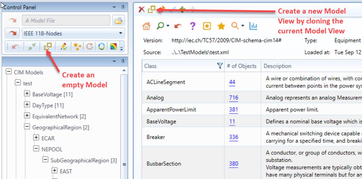
- View Creation: Users can create an empty model views or cloning an existing Model View, as illustrated below. Cloning an existing Model View is a very useful feature. It enables users to start model browsing from the current context.
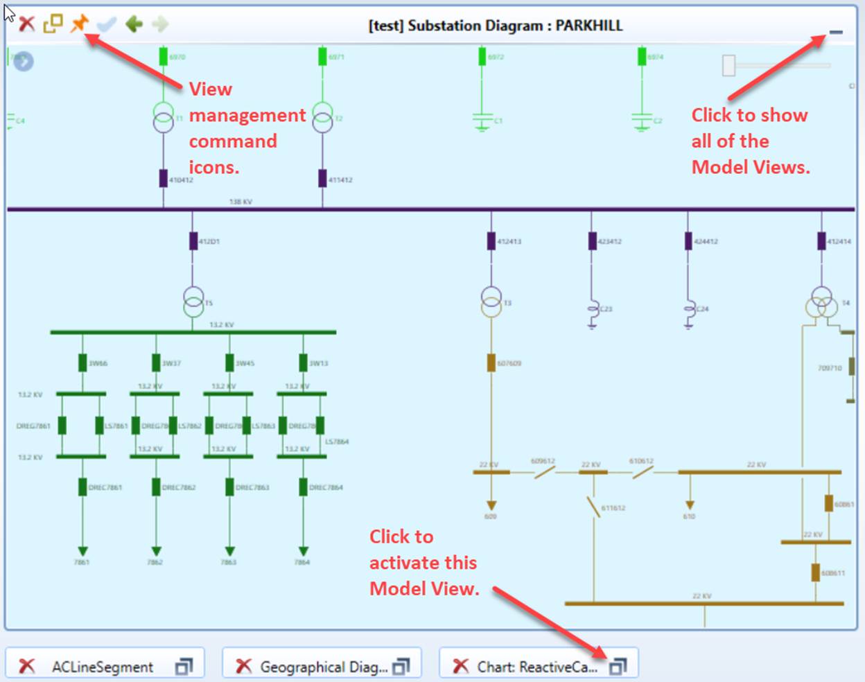
- View Management: Users can create multiple Model Views. They can be displayed simultaneously like tiles, or once at a time, as illustrated below. Additionally, the command icons in the view tile enable uses to manage the each Model View and navigate forward/backward.
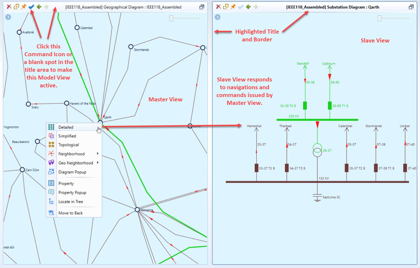
- Support of Master/Slave Navigation: While users can create multiple Model Views, only one of them can be active, responding to navigations from tree and other view. Users can make a Model View active by clicking the corresponding Command Icon or a blank spot in the title area. The Active Model View is characterized with a highlighted title and border, as illustrated below. Active Model View is also called Slave View, while other inactive views are called Master Views. The shared Slave View responds to the navigations/commands issued by any of the Master Views. The master/slave view support facilitates model browsing by allowing users to inspect the details without losing context. In the following example, the Master View displays a station/line diagram, while the Slave View displays the station on-line for the selected station in the Master View. Additionally, in-context diagram and property popup provides an alternative. It enables users to call a diagram or property display from the current display through popup, allowing users to drill down to the details without losing the context.
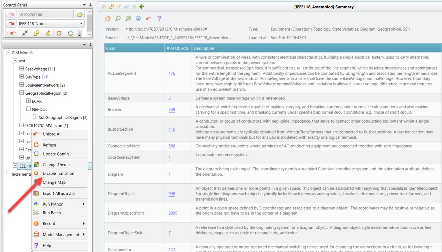
- Look and Feel: View transition is supported for better look-and-feel. By default, it is disabled. Users can enable view transition at run time or via configuration. Once enabled, the following transition mechanisms will be applied:
- Fade-in-out for view changing;
- Slide-and-zoom/right-to-left for backward navigation;
- Slide-and-zoom/left-to-right for forward navigation.
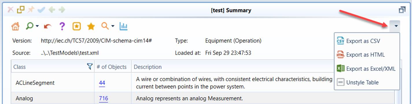
- Support of Exporting as Different Formats: The contents of Model View can be exported as different formats. More specifically,
- CSV, HTML, and Excel/XML for Form Displays and Tabular Displays;
- PNG for Chart Displays,;
- SVG and PNG for Diagram Displays.
Side Panel and Popup
Side Panel and Popup are designed to allow users to open a diagram or property display from the current view without navigating away. They provide relevant or detailed information within the same context, streamlining model browsing and facilitating model editing. Refer to Side Panel and Popup for more details.
Commands
Commands are issued to call/navigate to displays or invoke a model operation, such as model validation, model assembling, etc. Commands can be issued from
- Context Menus associated with the application, models, or modeling entities;
- Command Icons typically in the control panel or at the top of model displays;
- Hyperlinks in the model displays;
- Mouse Activities,such as mouse over or double-clicking of graphical symbols.
Context menu is the major way to issue a command. There are three types of context menus:
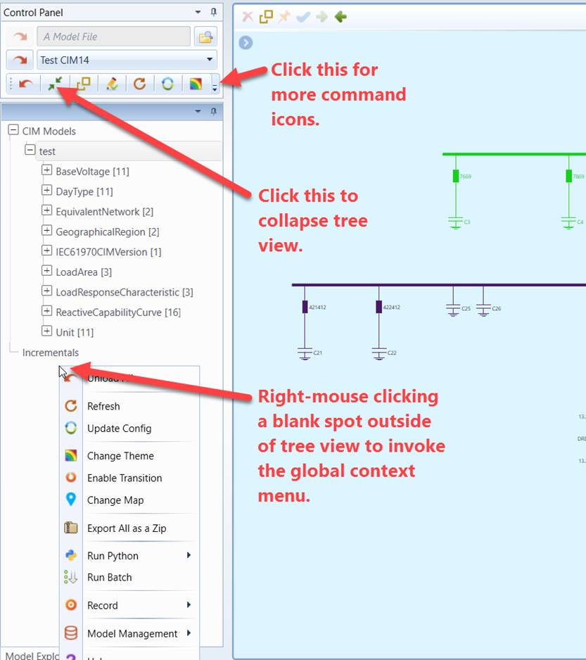
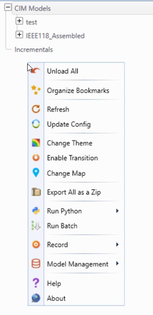
- Global Context Menus: for issuing comments at application level. These commands are not related to models. Global Context Menus can be invoked by right-mouse clicking an empty spot in the navigation tree panel, as illustrated below
- Model Context Menu: for issuing comments specific to a loaded model. Model Context Menus can be invoked by right-mouse clicking the model tree item in the navigation tree panel, as illustrated below
- Network Component Context Menu: for issuing comments specific to the selected network component, such as a Substation, equipments, etc. Network component context menus can be invoked by right-mouse clicking the tree items, graphical symbols/labels associated with the selected network component, as illustrated below.
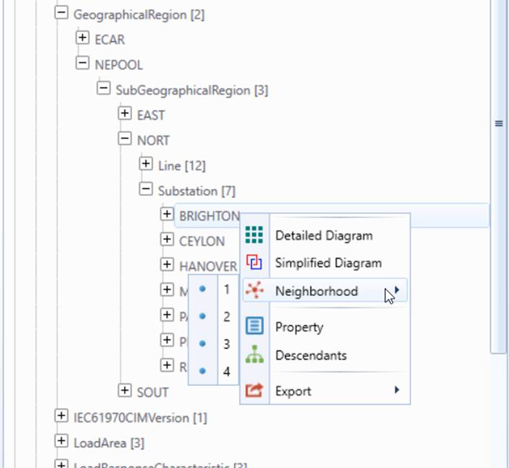
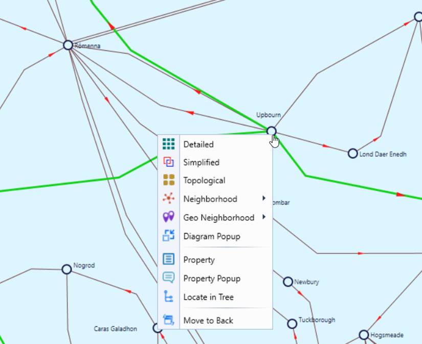
In summary, context menus are everywhere. If you want to do something, simply right-mouse clicking the proper UI elements and go from there.
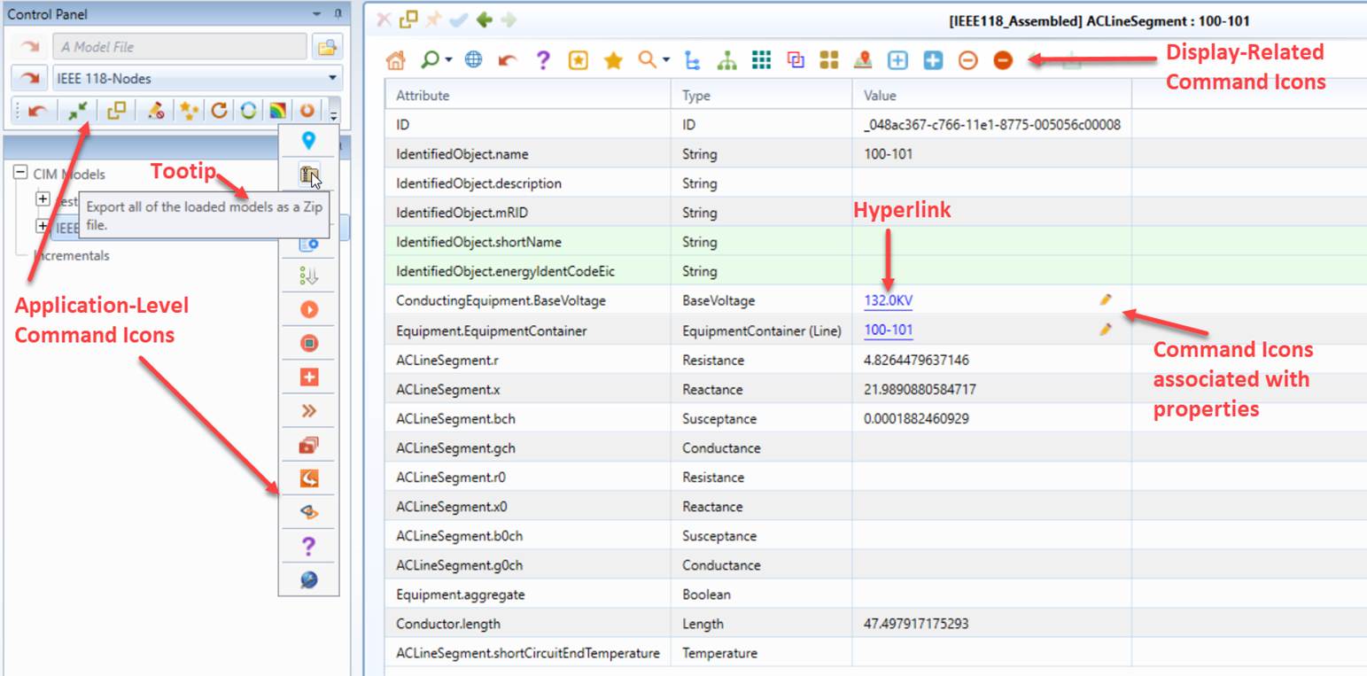
Icon buttons are also frequently used to enable users issue a command quickly. These icons are called Command Icons. Application-level Command Icons are found in the Control Panel, and display related Command Icons are typically located at the top of the displays as illustrated below. Each Command Icon contains a tooltip, which can be invoked by mouse-over the icon for a while.
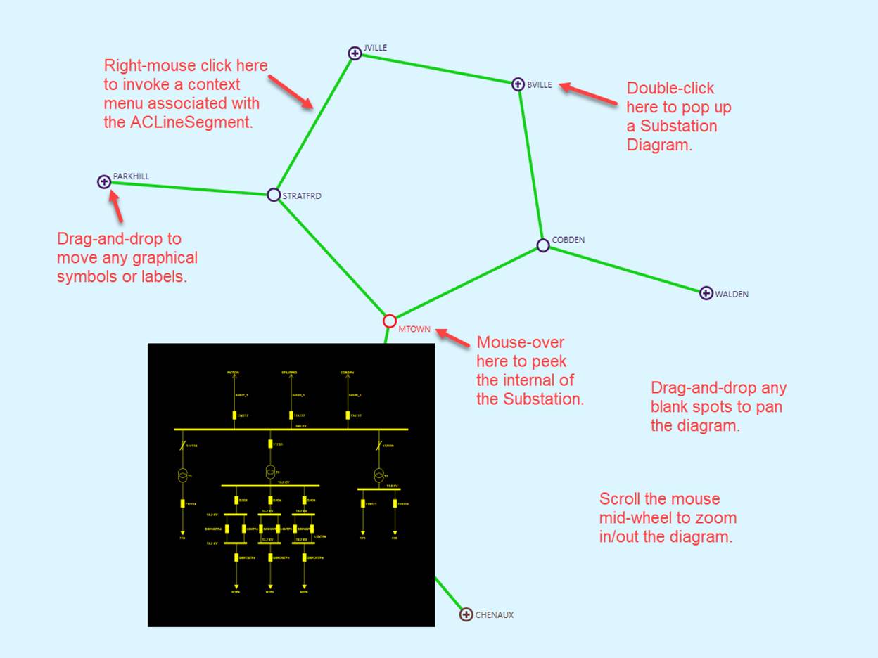
Additionally various types of mouse activities, such as left/right mouse clicking, mid-wheel scrolling, double-clicking, mouse-over, dragging-and-dropping, are used to facilitate navigation and interaction. In a Neighborhood Diagram, for example, users can quickly peek the neighboring substation diagram by moving the mouse over (mouse-over) the graphical symbol representing the neighboring substation. An animated popup will display the neighboring station diagram. Users can also navigate to the neighboring station diagram by simply double-clicking the graphical symbol representing the neighboring substation or invoking a context menu via right-mouse clicking on the selected neighboring substation symbol. The following screenshot illustrates some of the mouse activities supported in a Neighborhood Diagram.
Note
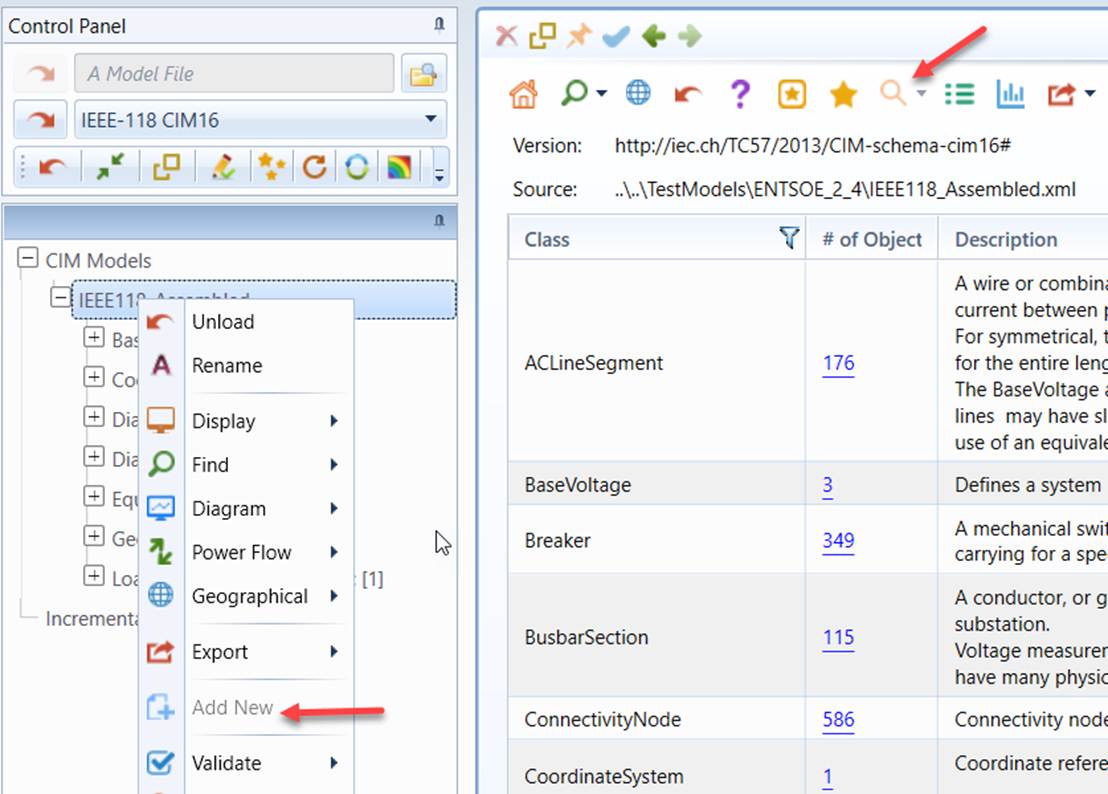
Both context menus are command icons are context-sensitive. They could be disabled or not displayed at all if the current context is not applicable. In the following example, the “Add New” context menu is disabled, because the Tool is not in the editing mode. The bookmark navigation command icon is disabled because there are no bookmarks available.
Tips
Users can invoke the global context menu by right-mouse clicking a blank spot in the tree panel. But the clicked bank spot must be completely outsied of the tree view. You may need collapse the tree to invoke the global context menu. But you don’t have to, since all of the commands can also be found from the command bar in the control panel, as illustrated below.