Network Topology Analysis (NTA)
Network topology analysis (NTA) is designed to help users improve the quality of model. The function is primarily used for
- Identifying the network topology errors. There are many ways to introduce the network topology errors. Manual model change is probably the most common cause.
- Identifying the unused network components (garbage) in the model. Such garbage is typically left during model maintenance. While the garbage network components are normally ignored by most network applications, they shall be removed from the model to avoid confusion and increase the size of the model. It is important to note that garbage collection is quite useful for the as-is operational model, this practice is normally not applicable to planning model. This is because planning model is designed for future. Many future projects may not be completely modeled yet or modeled as what-if scenarios. These future projects could be mistakenly identified as ‘garbage’. Thus extra caution shall be made to run NTA for the planning model.
Small network islands are typically resulted from either of the above two cases. NTA is designed to identify these small network islands from which users can trace the cause of these network islands. As part of model validation, fast network topology analysis enables you to detect and visualize physical, topological, and electrical islands at both station and node levels.
Physical Islands vs. Electrical Islands
NTA checks different types of network islands at various modeling granularities. More specifically, NTA identifies two types of network islands:
- Physical/Topological Island; A physical/topological island has no physical connections to other islands. Physical islands are for node/breaker islands, while topological islands are for bus/branch model. Physical connection are described using associations between Terminals and ConnectivityNodes ( for node/breaker) or between Terminals and TopologicalNodes (for bus/branch). Physical islands require only Equipment (EQ) information, while Topological Islands require additional Topology (TP) information.
- Electrical Island: An electrical island is electrically disconnected from the rest of the grid. An electrical island may be physically connected to other electrical island. But there is no power flow on any of the connection due to one of the following:
- Terminal.connected/ACDCTerminal.connected is’false’ (from TP); or
- Switch.open is ‘true’ (from SSH); or
- SvStatus.inService is ‘false’ (from SV).
As marked above, identification of electrical islands requires additional information from TP, SSH, or SV,
Depending on the type of the network models, NTA is performed at different levels. More specifically,
For Node/Breaker models, the following NTAs are performed to identify
- Substation Physical Islands: Each Substation is a node in this case. ConductingEquipments that connects two Substations (mostly ACLineSegments) are branches. The purpose of this type NTA is to find a Substation or a group of inter-connected Substations that are physically isolated from the rest of the grid.
- ConnectivityNode Physical Islands: Each ConnectivityNodel is a node in this case. ConductingEquipments that connects two ConnectivityNodel are branches. The purpose of this type NTA is to find physical islands at fine granularity. Note: a ConnectivityNode Physical Islands may not reside in a single Substation. It may span across multiple Substations.
- ConnectivityNode Electrical Islands: In the NTA searching for ConnectivityNode Electrical Island, only electrically connected branches are considered as connections between two ConnectivityNodes. A ConnectivityNode Physical Island may contain more than one ConnectivityNode Electrical Island.
For Bus/Branch models, the following NTAs are performed to identify
- Substation Topological Islands: Each Substation is a node in this case. ConductingEquipments that connects two Substations (mostly ACLineSegments) are branches. The purpose of this type NTA is to find a Substation or a group of inter-connected Substations that are physically isolated from the rest of the grid.
- TopologicalNode Topological Islands: Each TopologicalNode is a node in this case. ConductingEquipments that connects two TopologicalNodel are branches.
- TopologicalNode Electrical Islands: In the NTA searching for TopologicalNode Electrical Island, only electrically connected branches are considered as connections between two TopologicalNodes. A TopologicalNode Electrical Island is basically the same as TopologicalIsland in CIM.
For a Node/Breaker that contains Bus/Branch information, all of the above NTAs could be performed. The identified islands may become redundant in many cases. For example, a ConnectivityNode physical island that span across multiple Substations will also result in a Substation physical island. If TP/SV/SSH information is available, more islands could be reported. When this happens, users shall check focus on checking only one type of islands at one time.
Understanding NTA Reporting
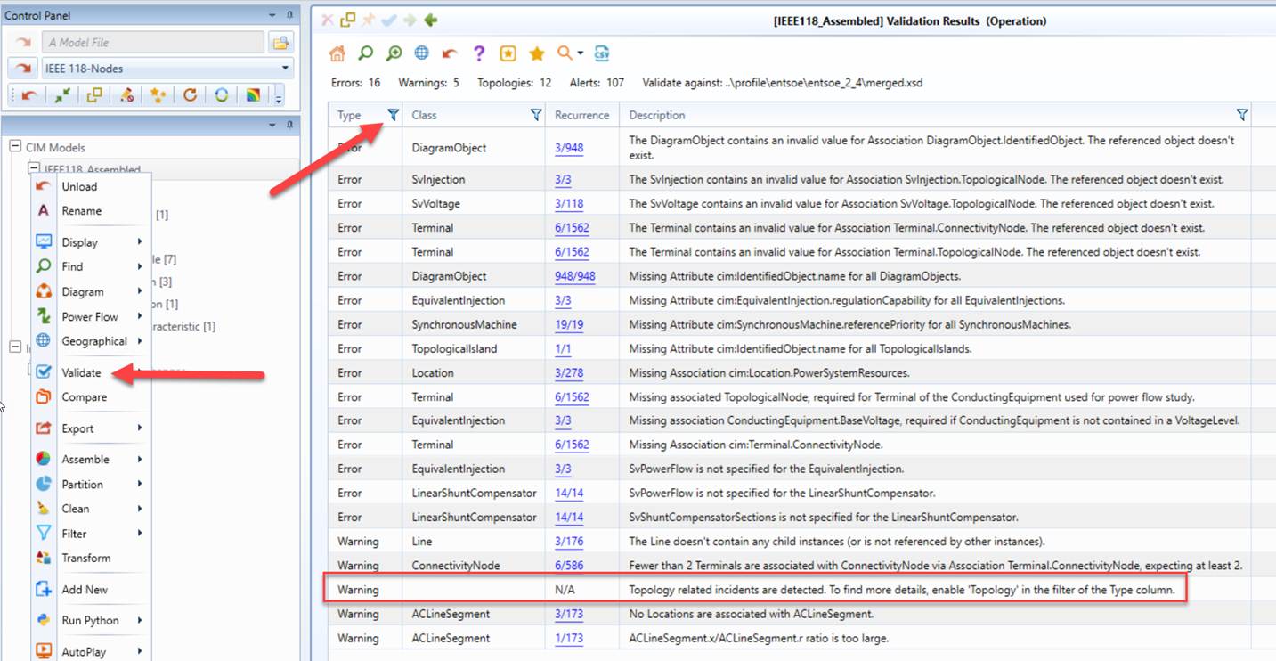
NTA is executed as part of model validation. The identified islands are reported in the model validation report. However, by default, the validation report doesn’t show them due to the fact that there are possibly many islands reported. Users will be prompted to inspect them by enabling the ‘Topology’ type of incidents, as illustrated below.
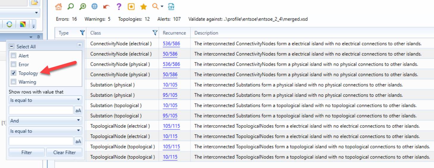
Users can further filter the incidents by Class and Description, as illustrated below.
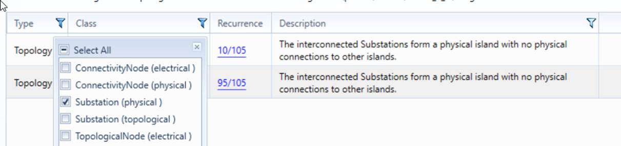
The following logics are applied for NTA island reporting:
- Only applicable islands are reported. For example, if the loaded model contains only EQ information, then electrical islands are not identifiable, thus not being reported.
- If only a single (main) island is identified, it will not be reported. This basically means all of nodes (Substations/ConnectivityNodes/TopologicalNodes) are (physically or electrically) interconnected.
- All of the single-node islands are grouped and reported as one incident.
- Multi-node islands are reported as multiple incidents, one incident per island.
The following sample illustrates the above reporting rules.

Visualizing NTA Results
NTA results can be visualized using the auto-generated Substation Diagram and Neighborhood Diagram.
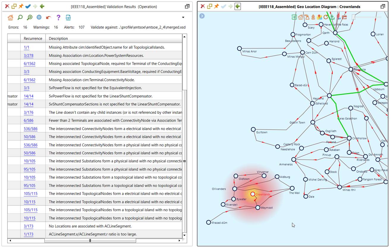
Starting from the model validation report, click the corresponding hyperlink to display the related nodes (Substations/ConnectivityNodes/TopologicalNodes) within an island.
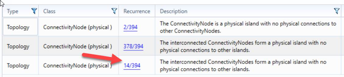
Navigate to one of the nodes (Substations/ConnectivityNodes/TopologicalNodes) within the island.
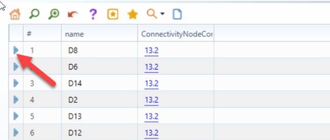
Call the corresponding diagram from the form display of the selected Substation/ConnectivityNode/TopologicalNode.
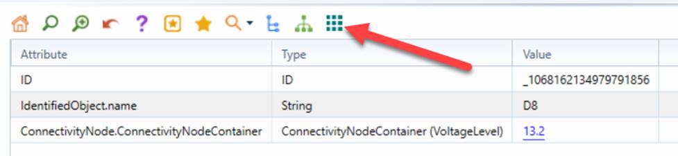
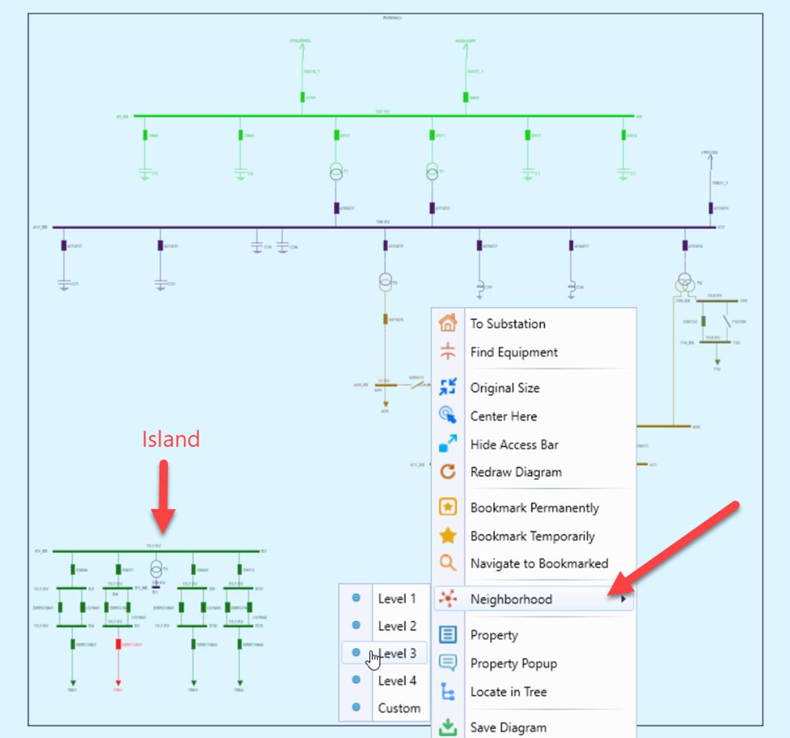
If the island is within a single Substation, it normally can be easily identified. The formed islands typically have no external connections, as illustrated below. If the island spans multiple Substations, users shall navigate to the neighboring Substations. Cross-station islands are not quite straightforward to visualize. Users shall use the Neighborhood diagram to navigate between Substations.