Standard Schematic Diagram
The Tool is capable of displaying standard schematic diagrams specified by IEC 61970-453. These diagrams are typically exported from other tools/systems. This feature enables users to reuse those elaborately designed one-line diagrams.
The diagram schematic layout profiled defined in the IEC 61970-453 standard simply defines graphical layout of a one-line diagram. A Diagram consists of a collection of DiagramObjects. Each DiagramObject contains one or more DiagramObjectPoints, etc. The diagram schematic layout information is typically exchanged separately from the domain models, such as Equipment model.
To display the standard schematic diagrams in the Tool, users must merge the diagram layout information separately exchanged with the domain models. This is because the diagram schematic layout profile is “loosely” defined. The tool may need additional information from the domain model to interpret the received diagram layout information. For example, if the received diagram layout data don’t contain DiagramObjectGluePoints, the tool must rely on the network topology information to derive the connectivity of DiagramObjects.
More specifically, to display a diagram that describes a node/breaker operational (SCADA/EMS) model, users must merge the Diagram model with the corresponding Equipment model. To display a diagram that describes a bus/branch planning model, users must merge the Diagram model with the corresponding Equipment model AND Topology model.
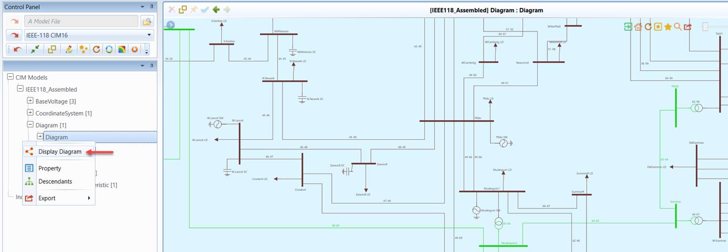
The standard schematic diagram can be displayed by clicking the tree item of the selected Diagram object or via context menu associated with the Diagram object, as illustrated below
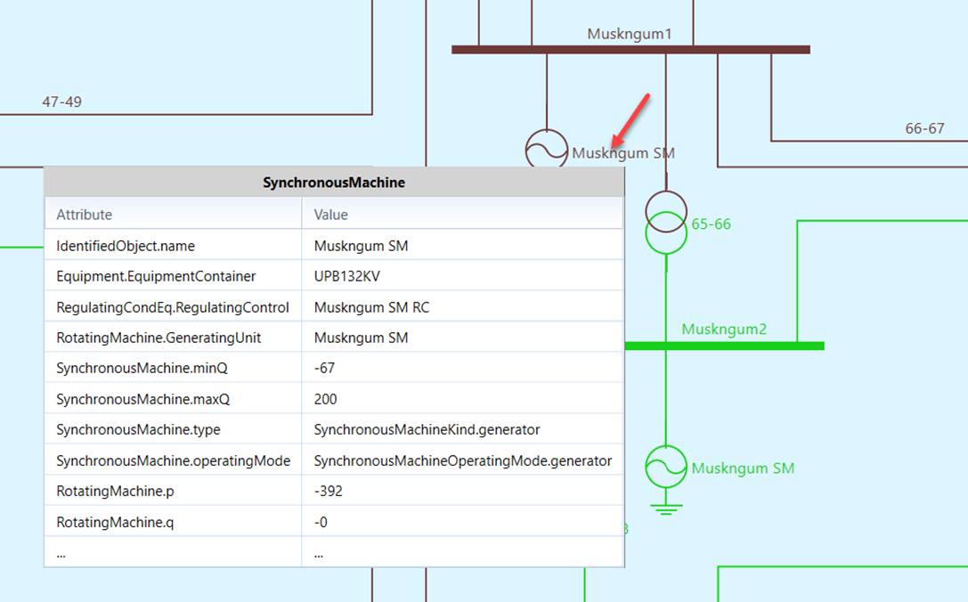
The graphical features of Standard Schematic Diagram are quite similar to those of the auto-generated Substation Diagram and Neighborhood Diagram. For example, users can zoom in the diagram and find out the detailed information about the selected equipment through a popup or by navigating to the property form of the selected object via a context menu. Some of the interactive features, however, are disabled for various reasons. For examples, users can not drag-and-drop graphical symbols or labels.
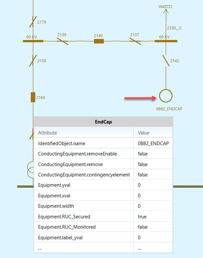
In the imported Standard Schematic Diagram, if the equipment is a ConductingEquipment NOT defined in the CPSM/ENTSO-E Equipment profile, it will be displayed as a generic equipment represented as a circle. In other words, any ConductingEquipments unknown to the Tool will be displayed as generic equipments.
Known Issues
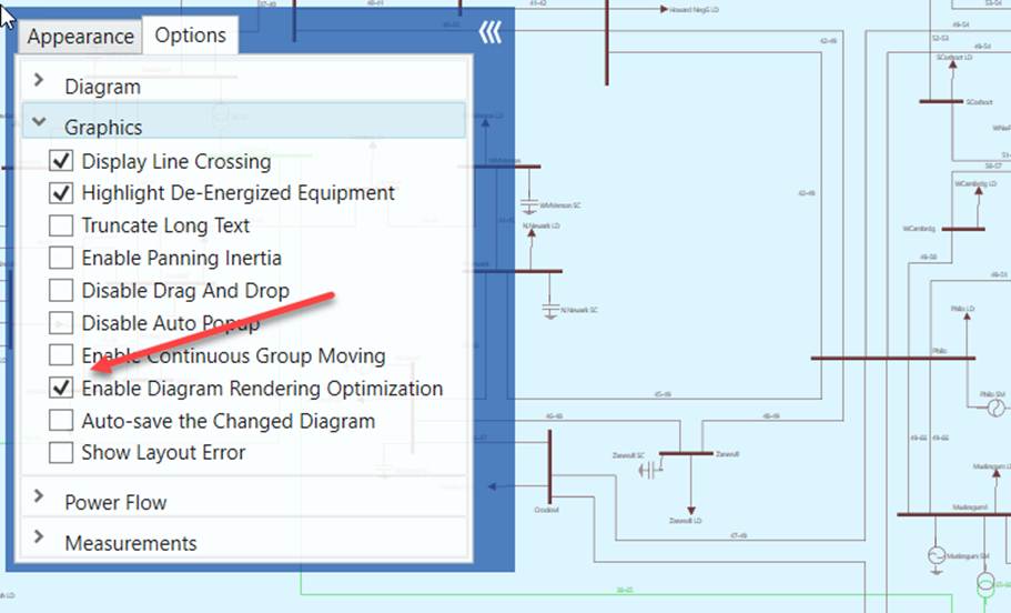
If your diagram is large, there will be a performance issue. It takes long time to render a large diagram. This is due to the limitation of .NET graphical support. You can mitigate this issue by enabling diagram rendering optimization as illustrated below. When this option is enabled, some of the time-consuming graphical components, such as power flow animation, measurements, etc., will not be displayed for large diagrams. The ultimatum solution, however, is to support diagram virtualization in the future release.