Adding a ConnectivityNode
ConnectivityNode is a special type of graphical modeling entity. A ConnectivityNode is where Equipment is connected. It is represented as a bus in a Substation Diagram. In many cases, a ConnectivityNode/Bus must be added prior to adding and connecting Equipment. A ConnectivityNode is treated as a special modeling entity. Users must provide the required initial information, i.e. voltage level, before a ConnectivityNode is added. Such information is critical for building the containment hierarchy for the added ConnectivityNode and subsequently the connected Equipment.
- Start with a detailed Substation Diagram and set up the graphical modeling environment.
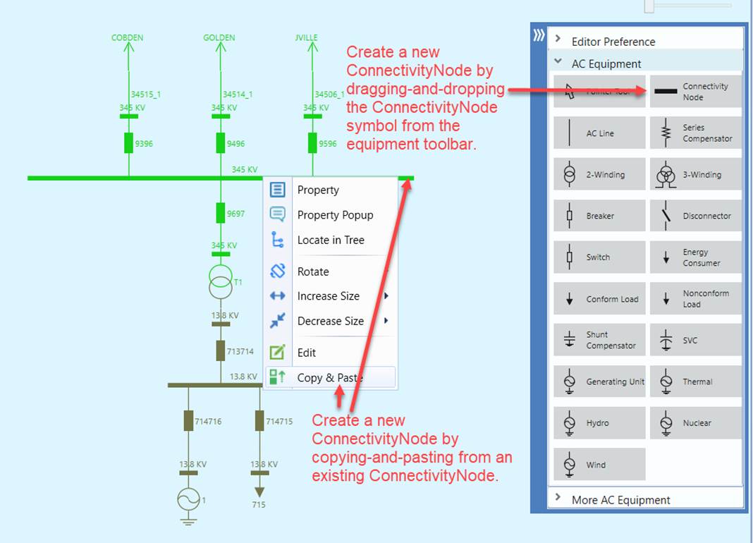
- Enter the entity-adding mode by selecting ConnectivityNode from the Components Panel or copying/cloning from an existing ConnectivityNode.
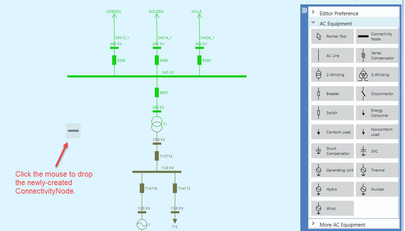
- Move the cursor to a blank spot and click the mouse to drop the ConnectivityNode to be added. In a dual-substation edit mode, users must drop the ConnectivityNode within the rectangular boundary of the targeted substation.
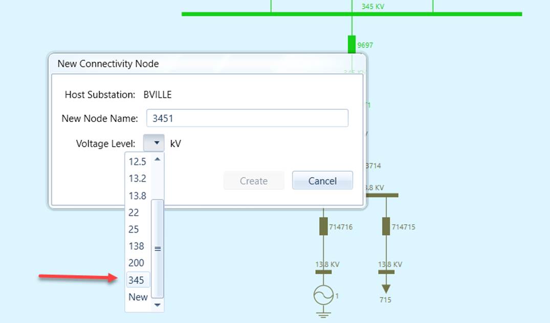
- If the new ConnectivityNode instance is initiated from the Component Panel, a dialog box will appear when users drop the new ConnectivityNode. Users must enter the minimal required information, i.e. voltage level. Such information can be either selected from the existing BaseVoltage list or entered as a new BaseVoltage. If the new ConnectivityNode is copied/cloned from an existing ConnectivityNode, the voltage level information is not needed. It is copied from the template ConnectivityNode.
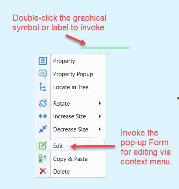
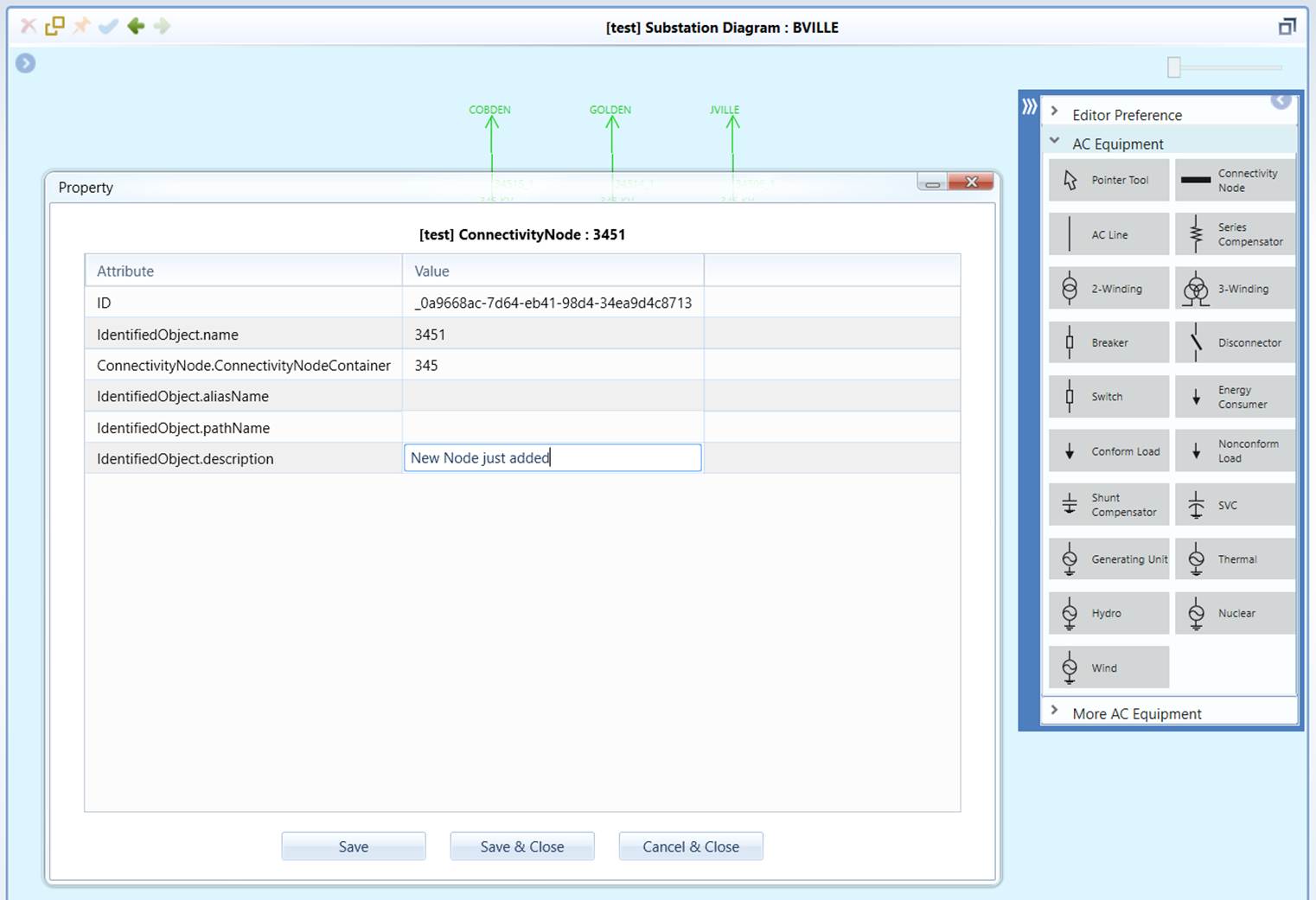
- Optionally, users can edit the newly-added ConenctivityNode in the modeling entity popup by double-clicking the new bus symbol/label or via the context menu associated with the new bus symbol/label. Click the Save button to commit the model editing.