Case Management, Logging, Configuration, and Debugging
Case Management
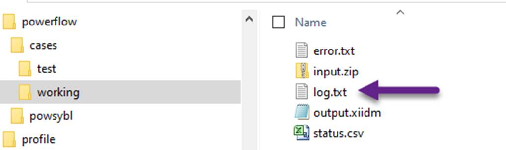
Folder \powerflow\cases is designated to store the cases. A case contains all of the information needed to run power flow, i.e. input.zip, as well as output, including output.xiidm, error.txt, log.txt, and status.csv.
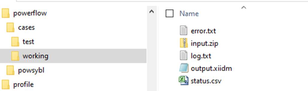
The ‘working’ case is dedicated to exchanging data between the Tool and the power flow engine, i.e. PowSyBl. It is important to note that all of the files will be automatically deleted before the next power flow computation. Thus if users want to keep the information, a separate case should be created and files should be moved from the working folder to this new case folder.
Logging
Power flow logging is enabled by default. The logging file can be found at \powerflow\cases\working\log.txt. .
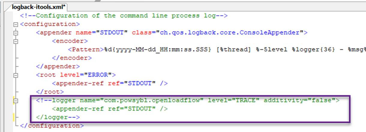
Logging is primarily used for supporting debugging. It adds some performance overhead. If you power flow solution is reliable, you can turn off logging by commenting the following block in \powerflow\powsybl\etc\ logback-itools.xml, as illustrated below:
Power Flow Related Configuration
Power flow related configurations are defined in \config\StandardConfig.xml, as illustrated below.
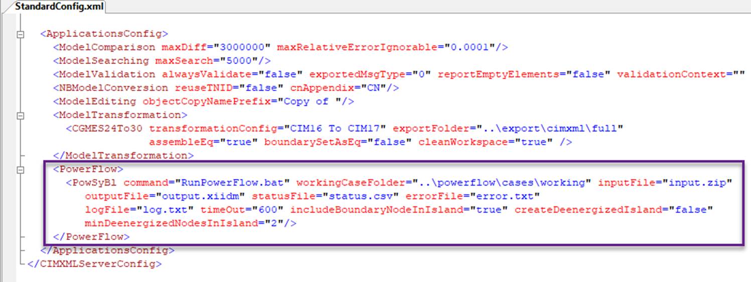
The configuration parameters are defined as following:
- command: batch file for executing power flow
- workingCaseFolder; the folder path of the working case where input/output files of power flow engine are stored
- inputFile: file name of the power flow input file
- outputFile: file name of the power flow output file
- statusFile: file name of the power flow status file
- errorFile: file name of the power flow error output
- logFile: file name of the power flow log output
- timeOut: time-out for power flow execution
- includeBoundaryNodeInIsland: if true, include boundary TopologicalNodes in IGM ToplogicalIsland.
- createDeenergizedIsland: if true, create de-energized island.
- minDeenergizedNodesInIsland: minumum de-energized nodes in island, only applicable when createDeenergizedIsland is true.
PowSyBl Configuration
The power flow computation is control by PowSyBl configuration file at \powerflow\powsybl\etc\config.yml. This is a YAML file. Most of the PowSyBl configuration parameters are by default, thus not listed in this configuration file. It only lists those that users might want to make changes. For complete PowSyBl configurations, please refer to www.powsybl.org/pages/documentation/simulation/powerflow.
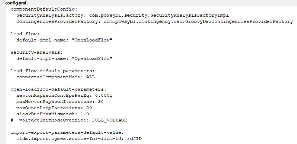
The configuration parameters listed in the YAML file are defined as below:
- connectedComponentMode: The valid values are MAIN or ALL. MAIN means only the main network is solved. ALL means all of the networks (islands) are solved. The default value is MAIN.
- newtonRaphsonConvEpsPerEq: a stopping criteria for the Newton Raphson iteration. The value is per equation and in per unit. It is kind of average mismatch tolerance for all quantities (like bus p and q). The default value is 0.0001.
- maxIteration: The maximum number of iterations. After reaching the maxIteration, the power flow computation will be aborted. The default value is 30.
- slackBusPMaxMismatch: the maximum active bus mismatch in MW, a criteria to stop slack distribution. The default value is 1.0 MW.
- voltageInitModeOverride: When at FULL_VOLTAGE mode, voltage angles calculated from a DC power low and voltage magnitudes calculated from a simple linear model are used to initialize the state variables prior to Newton Raphson iterations. In other words, it enables AC power flow to start from a better initial guess, improving the chance of getting a converged solution. By default, the FULL_VOLTAGE mode is disabled.
Other configuration parameters in the YAML file shall bot be changed. For example, configuration parameter iidm.import.cgmes.source-for-iidm-id must be specified as rdfID. By default the MRID is used in the output file. Intergartion with PowSyBl, however, relies on rdfID. Thus this configuration parameter must be set as rdfID.
Debugging
When power flow fails to solve or diverges, it is time to find the cause and fix it if possible. The process is called debugging. There are a few potential causes that result in a failed or diverged power flow solution:
- There are road-blocking issues in the model, such as incorrect and unrealistic equipment parameters, unbalancable load demand, unreachable regulation targets, etc. While model validation reveals some of these issues, not all of the issues can be identified. In fact, some of the deep modeling errors can only be discovered through power flow. In general, modeling error is the most possible reason.
- There are defectives or limitations in the power flow engine, i.e. BowSyBl. Some of them have been discovered and described in Known Issues.
- Improper configurations, for example, the maximum iteration number is inadequate. See PowSyBl Configuration above.
Debugging is a challenging process requiring some deep knowledge about the model and power flow algorithm. Here are some tips that may offer some insight:
- If the power flow fails to solve,
- An error message is normally popped up. The error message normally provides the direct reason.
- For more detailed, check the log file and search for ERROE.
- If power flow diverges,
- If the max bus mismatch is not significant, consider increase configuration parameter maxIteration, or stopping criteria. Note: changing configuration parameter newtonRaphsonConvEpsPerEq is a little dangerous.
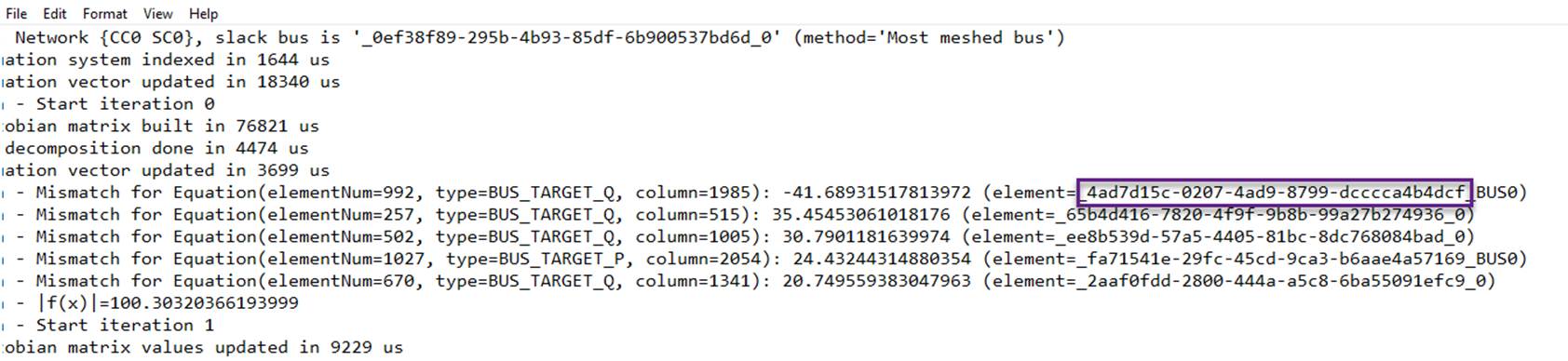
- Check the log file to find the buses where the large bus mismatches occur. These are normally the location where modeling errors occur nearby.
- Always look at the first a few iterations. Bus mismatches will spread after the first a few iterations.
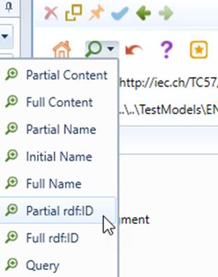
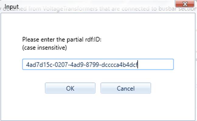
- PowSyBl names bus ID as PowerTransformerID_BUS0 or VoltageLevelID_0. So search for PowerTransformerID/ VoltageLevelID in the Tool, rather than full bus ID, (i.e. _4ad7d15c-0207-4ad9-8799-dcccca4b4dcf, rather than _4ad7d15c-0207-4ad9-8799-dcccca4b4dcf_BUS0, as illustrated)