Importing/Exporting Geographical Data in a User-Defined Format
Geographical diagrams require the model contain the geographical data, such as Substation/ACLineSegment locations in longitude and latitude. Such information is typically stored separately from the model, for example in GIS. Additionally, the raw geographical data are most likely NOT in the CIM format. The Tool provides a capability to enable users import/export the geographical data in a user-defined format. Furthermore the Tool is capable of reducing the size of the imported geographical data to improve the performance of geo diagram rendering.
Defining the Geo Data Import/Export Format
In CIM, the geographical data, i.e. Locations, are associated with PowerSystemResources (i.e. Substation/ACLineSegment) through rdf:IDs. Thus, the easiest way to import/export geographical data is using the rdf:IDs as identifiers. Unfortunately, the rdf:IDs are normally not persistent cross-systems. For example, the GIS may not contain the rdf:IDs generated by the EMS modeling system.
Names appear to be more practical to associate geographical data with the equipment model. In many cases, GIS and EMS use the same naming convention to name the substations and equipment. Even names don’t match exactly, a mapping table can be relatively easy to build and maintain, because names are human-friendly.
On the other hand, names are less reliable. They could be duplicated especially if the model is assembled from different sources. In order to use names as identifiers, users may have to identify a Substation/ACLineSegment using multiple names. For example, Substations are uniquely identified using two names: name of the host GeographicalRegion and name of the Substation.
Realizing it is infeasible to build one-size-fit-all geo import/export format, the Tool supports a user-defined format that allows users to import/export the geo data in a way fitting their specific naming conventions. Unfortunately nothing comes for free. This support requires users to configure the Tool to support their specific formats unless their geo data are in the default formats supported by the Tool. Note, the geo import configurations are shared by all of the loaded models.
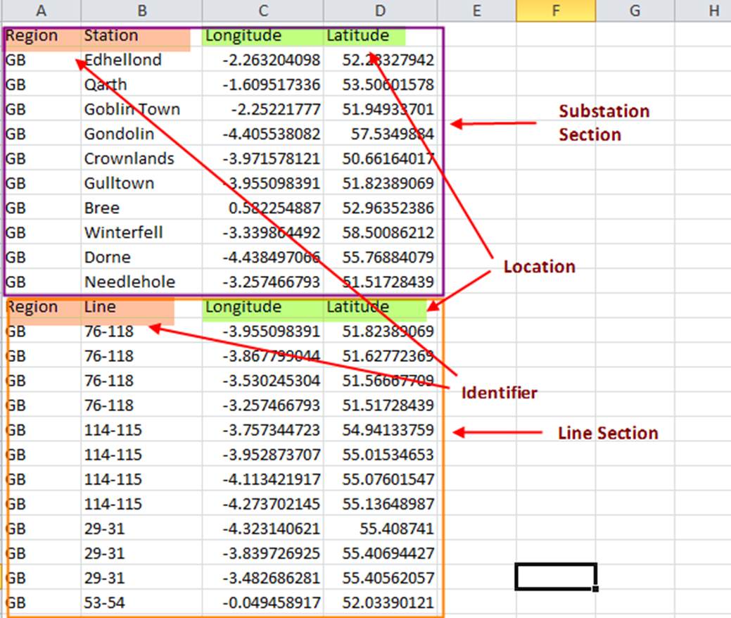
As a general guideline, the user-defined formats must be a flat table, normally a CSV file. It contains up to two sections: one for Substations (required) and the other for line segments, i.e. ACLineSegment/DCLineSegment (optional). Each section must contain two groups of data: identifiers and locations. The locations, i.e. longitude and latitude, are fixed, while the identifiers are configurable. The following figure illustrates the supported format.
Identifiers are configurable. They can be declared using MQL in CustomConfig.xml under CIMSpy\config, as shown below:
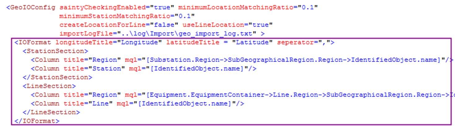
Where:
longitudeTitle – Title of the longitude column in the flat table, applicated to both StationSection and LineSection.latitudeTitle – Title of the latitudecolumn in the flat table, applicated to both StationSection and LineSection.seperator – Seperator used to separate two fields in the flat table.Column/title – Title of the identifier column.Column/mql – MQL string used to map to station/line attribute.Column/infoOnly – optional flag to indicate whether this column is information-only. If true, the column will not be treated as identifier.
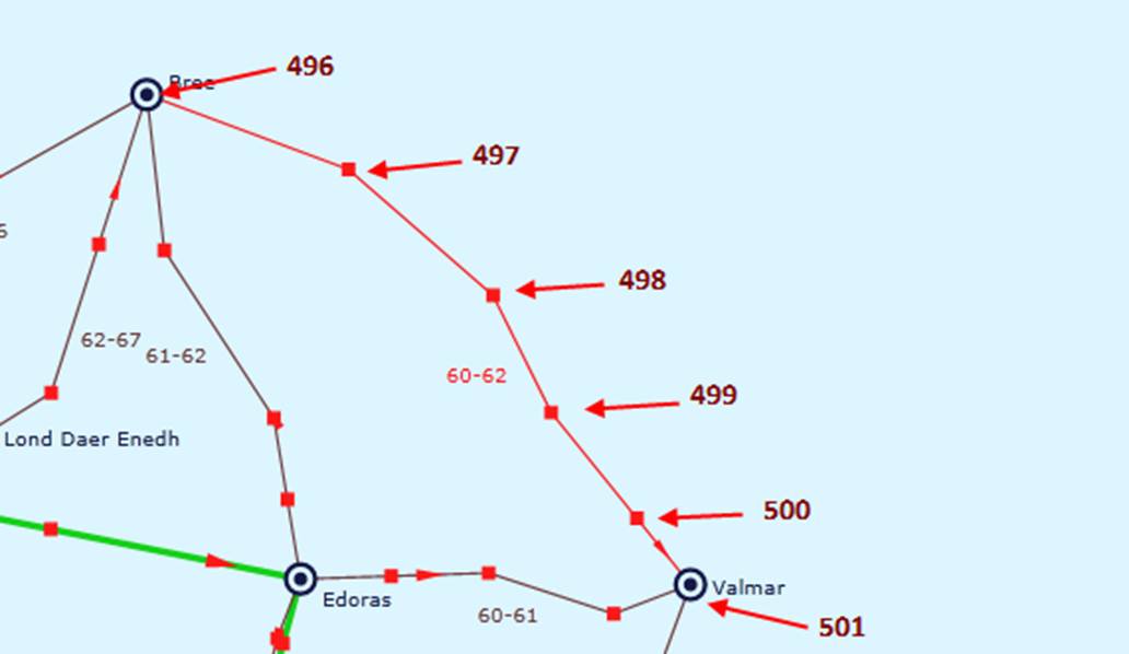
It is important to note that the line segments that belong to the same line must share same identifers and the points MUST be consective in sequence. For example, the following line points in the import geo file
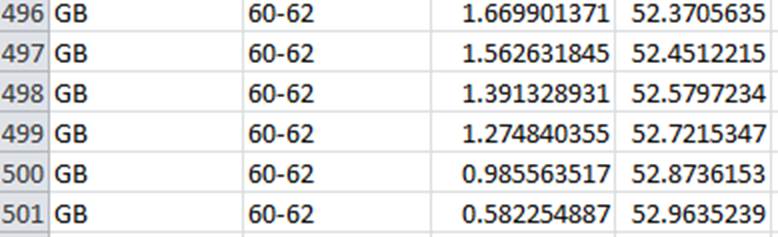
will be displayed as below with point indexes marked.
The defined format can be used for both geo data import/export. During the import, the Tool will find the record matching each of the declared identifiers except those that are declared as “infoOnly”. Once matched, the imported location will be converted to the CIM format. Note: in the case where mutiple Identifier columns are declared, all of the none-infoOnly columns must be exactly matched. The import geo flat table may contain any other columns. The Tool will just ignore them. Also the column sequence doesn’t matter. The Tool uses the “title” attribute to find the declared identifier columns. The Tool also comes with a default format where Substation/AcLineSegments names serve as the only identifiers. This default format is built-in, even without any decalartions in the configuration file. If you decide to use the default format, you have to make sure that Substation/AcLineSegments names are unique modelwise. Otherwise, you need add other columns such as GeographicalRegion/SubgeographcalRegion name columns. If you have rdf:IDs, then you just need delcare a single columns as follows

In the user defined format, it is expected that each field is separated by a separator. Assuming the separator is comma, i.e. ‘,’, the substation locations will be specified as follows
Region,Station,Longitude,Latitude
GB,Edhellond,-2.2632040977478027,52.28327941894531
If the field contains the separator, you will have to enclose the contents within double quotation marks, i.e. “. For example
GB,”Edhellond, Qarth”,-2.2632040977478027,52.28327941894531
The traditional fixed length format is supported in a generic way with separator defined as blank, (i.e. separator=” “). A blank separated format is handled a little differently. The imported line is pre-processed. Additional blanks between two fields are ignored. For example, the following line
GB Edhellond -2.2632040977478027 52.28327941894531
is prepressed and treated the same as
GB Edhellond -2.2632040977478027 52.28327941894531
This mechanism supports any fixed size formats, assuming no fields can be blank.
Import of Geo Data
If the imported EQ model doesn’t have geo data, users can invoke the geo import function as follows:
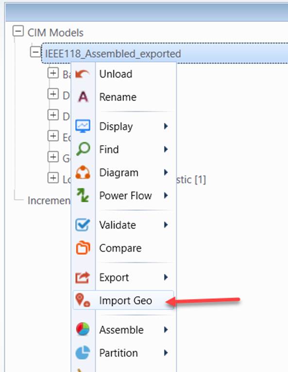
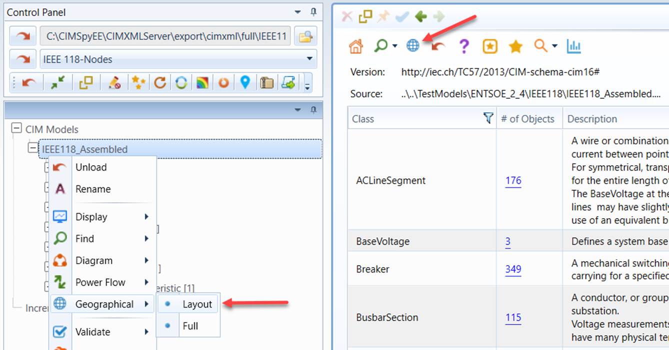
Once imported, the geo data will be converted to CIM format and merged with EQ model. Users will be prompted to save the merged model into a different file. Then the geographical diagram will be available through context menu or command icon, as illustrated below.
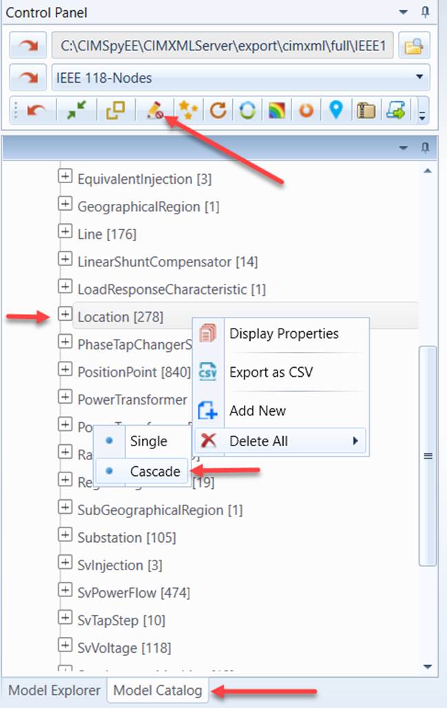
If the model already contains the geo data, the Tool will disable the geo import functionality. In this case, in order to import the geo data, users must cascading-delete all of Locations, save the model and then reload the model in order to enable the geo import function.
Note
the geo import function is available for any supported versions of CIM despite the fact that CIM geo profile is defined for CIM 16.
There are a few configuration parameters that can be modified to change the behavior of geo data import process. These configuration parameters are defined in the GeoIOConfig element, as illustrated below:

Where
saintyCheckingEnabled: If true, the import algorthm will check the matching between GEO and model, import algorrihm will abort if the matching ratio is smaller than the minumum ratio specifed.minimumLocationMatchingRatio: Minmum geo matching ratio (matched geo location/total geo location), required if m_saintyCheckingEnabled is true. Import process will abort if the matching ratio is smaller than the minumum ratio specifed.minimumStationMatchingRatio: Minmum station matching ratio, (matched station/total station), required if m_saintyCheckingEnabled is true. Import process will abort if the matching ratio is smaller than the minumum ratio specifed.createLocationForLine: Flag used to control whether to create Locations for lines without geo data.useLineLocation: Flag used to control whether to use geo data to create line Location.importLogFile: Import log file path.
Export of Geo Data
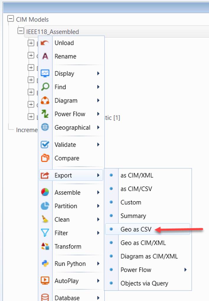
The geo data in CIM format can also be exported as a flat file in a specified format, ready to be consumed by other tools/systems not supporting CIM format. This format of the exported file will be exactly like what is defined in the format specification. It will include all of the columns, including infoOnly columns.
Logging of Inconsistencies
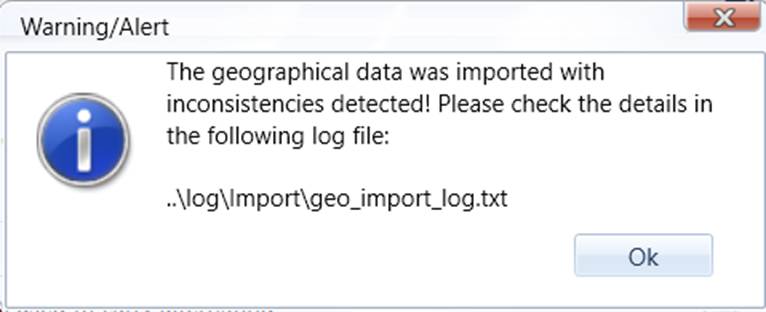
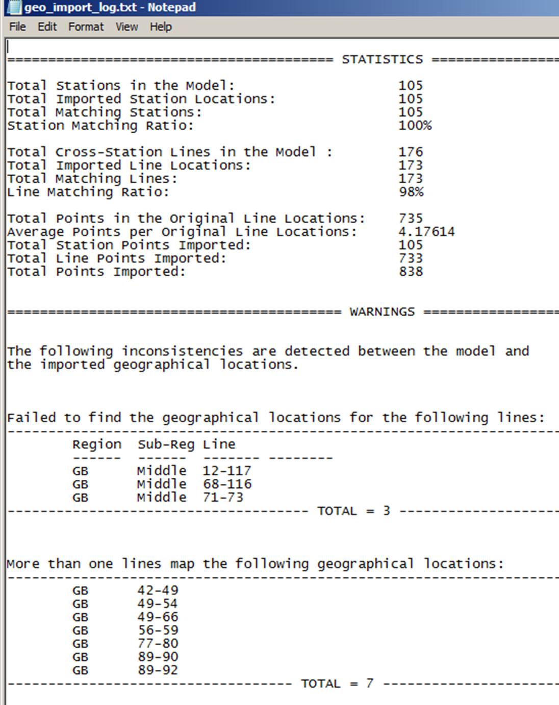
If there any inconsistencies between the imported geo data and the model, a log file will be created to record all of the detected inconsistencies.
Reduction of Geo Data Size
If your geo data come from GIS, they may contain very detailed geo information, including locations of transmission towers. Such detailed geo information may create a performance burden for diagram rendering. The Tool provides users an option to reduce the size of the imported geo data. When enabled, this function will combine the line geo locations to reduce the size of the imported geo data. Multiple segment positions may be combined as single line segment positions if they fit certain criteria, as illustrated below:
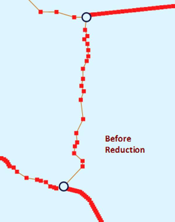
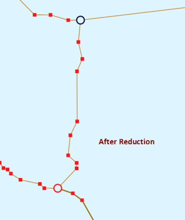
In the above diagram, each red point is a PositionPoint imported. As shown in the above diagram, the line routes are mainly kept, but the PositionPoints are significantly reduced, thus enhancing the diagram rendering performance. The reduction ratio is logged in the log file
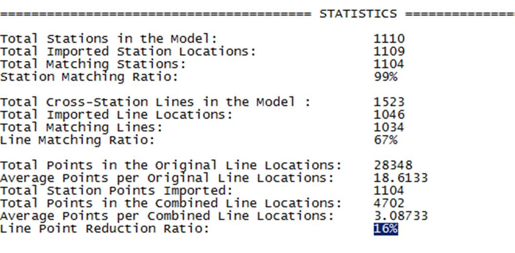
The geo reduction algorithm is controlled by a set of parameters specified in the GeoReductionConfig, as shown below

Where
linePointReductionEnabled: If true, the algorithm will combine small line segments based on the criteria to reduce the number or line PositionPoints.minimumPointsToTriggerReduction: If number of line points exceed the specified minimum number and m_reduceGeoLinePoints is 'true', and the average point/line ratio exceeds minimumPointLocationRatioToTriggerReduction, the line segments will be reduced.minimumPointLocationRatioToTriggerReduction: if the average point/line ratio exceeds minimumPointLocationRatioToTriggerReduction, and number of line points exceed the specified minimum number and m_reduceGeoLinePoints is 'true', the line segments will be reduced.directLineConnection: if true, location points on the lines are ignored. Stations will be connected by straight lines.angleTolerance: Minimum angle (in radian) used to straighten the sloped lines.straightLineTolerance: Maximum number of pixels used to straighten horizontial or vertical lines. If the Y or X of two points is below the specified maximum number of pixels, the two points will be adjusted as horizontal or vertical.equalPointTolerance: Coordinate overlap tolerance in both x and Y.multiLineAngleTolerance: Minimum angle (in radian) used to straighten the sloped multi-lines.multiLineStraightLineTolerance: Maximum number of pixels used to straighten horizontial or vertical multi-lines. If the Y or X of two points is below the specified maximum number of pixels, the two points will be adjusted as horizontal or vertical.multiLineEqualPointTolerance: Coordinate overlap tolerance in both x and Y for multi-lines.
Note geo reduction configuration is a global setting shared by all of the loaded models. It is also used forGeographical Diagrams rendering.