Model-View-ViewModel (MVVM) Support
Common Information Model (CIM) is primarily designed to facilitate model exchange between different systems and applications in the power industry. It provides a standardized framework for representing power system components, relationships, and attributes, ensuring interoperability across various platforms.
However, a modeling tool that strictly follows CIM modeling principles may not be user-friendly for practical use. While CIM ensures consistency and standardization, it does not inherently prioritize ease of use, intuitive data visualization for end-users. The major identified gaps include:
- CIM is highly fragmented - CIM models are extremely granular, representing the power grid and its operations at the finest level of detail. While this modeling approach offers flexibility and generality, it can make interpretation complex. Users often need to link multiple entities to construct meaningful representations. For example, a complete representation of a transformer requires more than a dozen CIM objects.
- CIM is not engineer-friendly - While CIM is designed to facilitate data exchange and interoperability, it is not inherently engineer-centric. For example, engineers typically prefer using per-unit (PU) representation for line parameters, as it simplifies calculations and comparisons across different voltage levels. In contrast, CIM adopts engineering units, such as Ohms, Siemensto maintain generality and standardization. However, this difference in representation can make it cumbersome for engineers to work directly with CIM-based models without additional data processing or customization.
To address these gaps and other customization needs, the Tool provides a meta-data driven solution based on Model-View-ViewModel (MVVM), a software architectural pattern. The MVVM support provided enhances flexibility, usability, and customization, making a CIM-based modeling tool more user-friendly by allowing dynamic adjustments to the UI and data presentation without modifying the core CIM structure.
About MVVM
Model-View-ViewModel (MVVM) is a software architectural pattern that separates an application’s logic, user interface (UI), and data management, enhancing maintainability, scalability, testability, and customizability. One of the benefits of MVVM is its support of meta-data driven UI customization, allowing users to build user-friendly UI.
Following the Model-View-ViewModel (MVVM) design pattern, the User Interface (UI) should be separated from the underlying data model through a ViewModel. This separation ensures a clear distinction between data, business logic, and UI presentation, making the application more maintainable, testable, scalable, and customizable. Key Components of MVVM include:
- Model (M) – Represents the data layer and business logic. It defines how data is stored, retrieved, and processed.
- View (V) – Represents the user interface that displays data and interacts with the user.
- ViewModel(VM) – Acts as an intermediary between the Model and View, handling UI logic and data binding and mapping without directly manipulating the View.
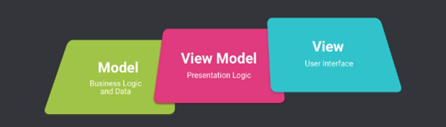
By implementing MVVM, developers can create modular, maintainable, and scalable applications with a clean separation between the UI and business logic. One of the benefits of MVVM is its support of meta-data driven UI customization, allowing users to dynamically adjust the user interface based on meta-data configurations rather than hardcoded UI layouts. This enables flexible, adaptive, and user-friendly presentations of underlying data in a way that is familiar and intuitive to end-users.
More specifically, the Tool provides:
- Built-in MVVM Support: The Tool automatically groups fine-granular CIM objects and presents them as a whole.
- Custom MVVM Support: Users can define how the CIM model should be presented through meta-data configuration.
Built-in MVVM Support
This is the default MVVM support. In this approach, the Tool automatically groups fine-granular CIM objects and presents them as a whole, ensuring a more structured and intuitive representation of the model.
More specifically, instead of requiring users to manually link multiple CIM objects, the Tool infers the ViewModel dynamically based on either discovered or user-specified model hierarchies. This enables related CIM entities, such as equipment, measurements, and operational limits, to be logically grouped and displayed together in a Composite Form Display, specifically designed for presenting and editing complex objects and allowing users to interact with multiple related CIM elements in a single, unified interface. This approach streamlines model browsing and editing, improving usability and efficiency in CIM-based workflows.
As an example, the following shows how a PowerTransformer and its 12 descendant CIM objects, including PowerTransformerEnd, Terminal, RatioTapChanger, Analog, OperationalLimitSet, and ApparentPowerLimit, are presented in a Composite Form Display.
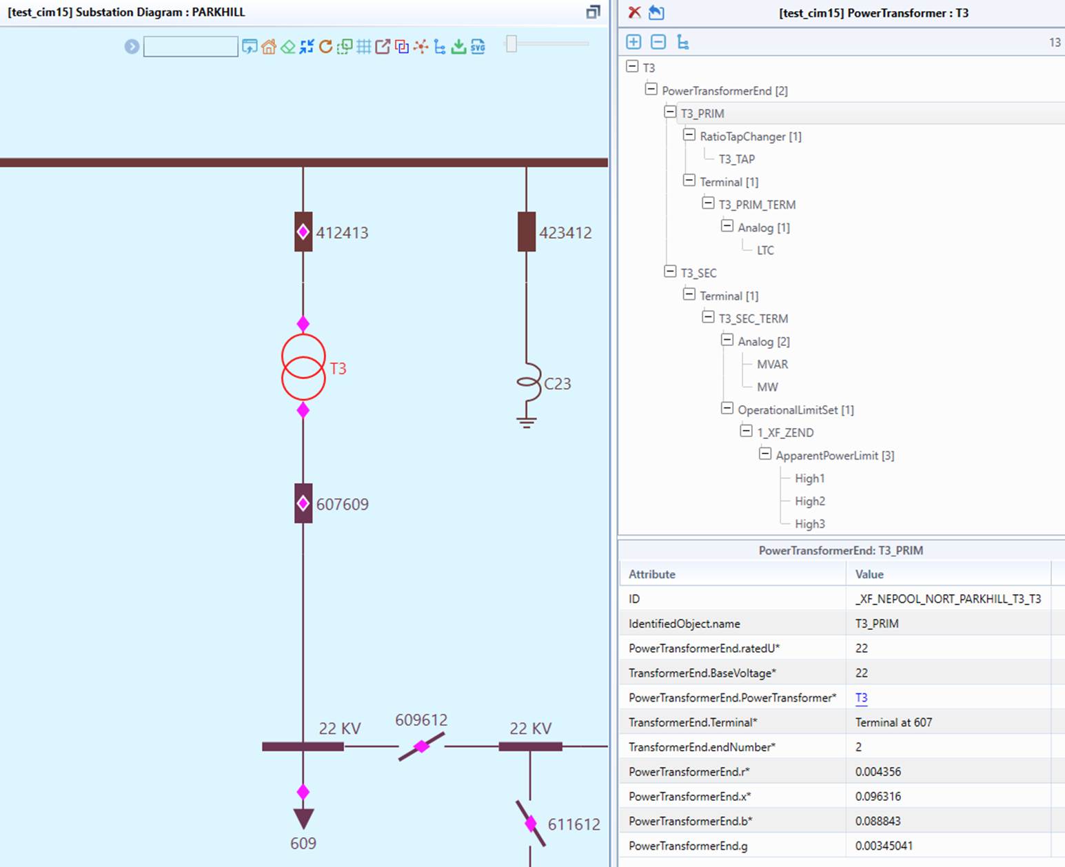
The behavior of the Built-in MVVM Support can configured by modifying \config\viewmodel\ DefaultViewModel.xml, as shown below.
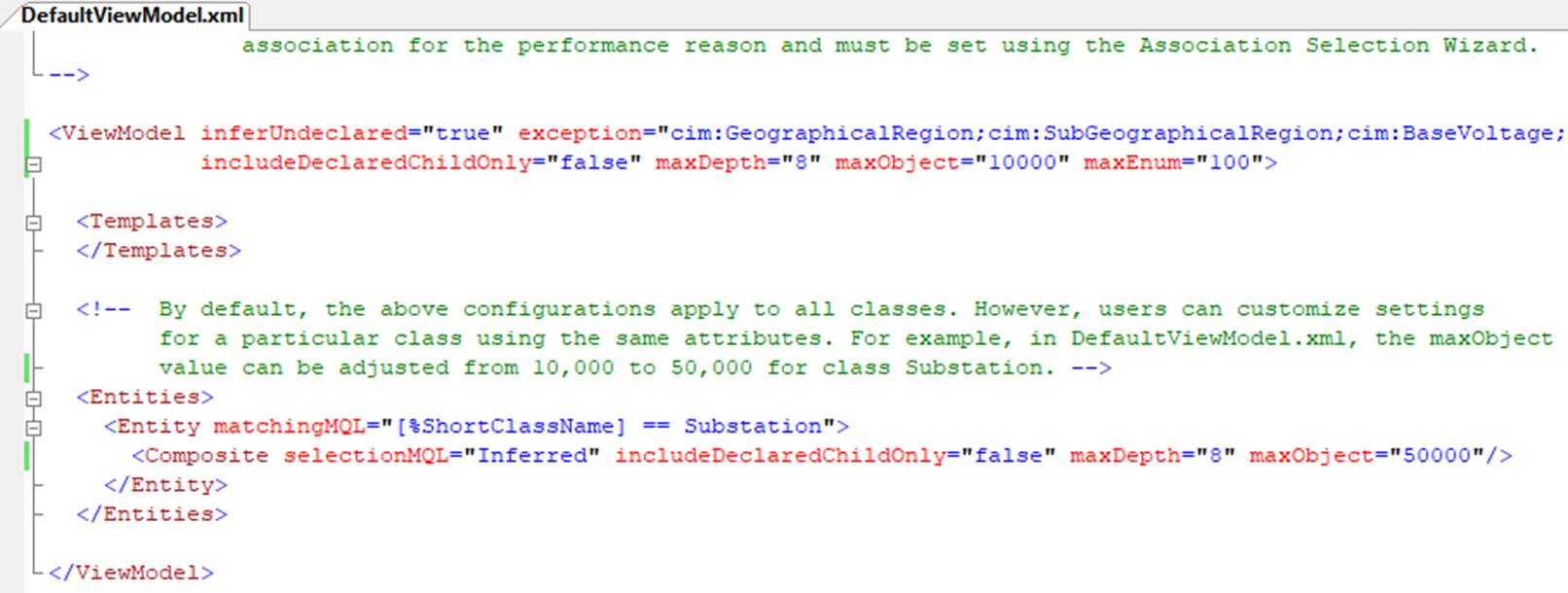
The configurable attributes include:
- inferUndeclared: if set to true, a ViewModel will be automatically inferred for any classes that are not explicitly declared in this definition. All other attributes are meaningful only when this attribute is set to true.
- exception: Specifies the names of classes that should not be inferred, separated by a ‘;’ delimiter. The exception list allows certain classes to be excluded from ViewModel inference, primarily for performance optimization by preventing unnecessary ViewModel generation for specified classes.
- includeDeclaredChildOnly: If set to true, only declared child objects will be included during the inference of associated objects. The declared children are specified in the \config\constraint\DefaultConstraint.xml file, ensuring that only predefined relationships are considered during ViewModel inference. This helps control the scope of inferred objects, improving performance and maintaining consistency. During object editing, only declared children are included even this attribute is set to false. This is essentialto properly support cascading deletion and deep-copy. In other words, this attribute only works during read-only mode in UI. By default, this attribute is set to false to facilitates model browsing, as it removes restrictions on exploring the models.
- maxDepth: Defines the maximum depth level to be considered during the inference of associated objects. This parameter controls how deeply related objects are traversed, preventing excessive recursion and improving performance by limiting the complexity of inferred relationships.
- maxObject: Specifies the maximum number of associated object tree nodes that can be serialized to prevent performance penalties. If the number of the associated objects exceeds this limit, the inference process will be aborted.
- maxEnum: Specifies the maximum number of enumerated reference objects to prevent performance penalties. If the associated object is a shared root object in the Model Explorer navigation tree (referred to as unstructured object), such as BaseVoltage, LoadResponseCharacteristic, it can be set from a dropdown in the UI. This is the quickest way to set an association property. However, if the number of the referenced objects exceeds maxEnum, it is treated as a regular association for the performance reason and must be set using the Association Selection Wizard.
- lazyLoadThreshold: When the number of associated descendant objects exceeds this threshold, the object is considered “heavy,” and lazy loading of the associated objects is triggered to significantly reduce the loading time of the Composite Form.
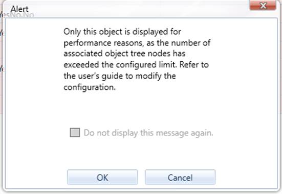
By default, the above configurations apply to all classes. However, users can customize settings for a particular class using the same attributes. For example, in DefaultViewModel.xml, the maxObject value can be adjusted from 2,000 to 10,000 for class Substation. If the number of associated object tree nodes exceeds this limit, the association objects are not displayed for performance reasons. In this case users will be alerted, as shown below.
Note:
- The inferred ViewModel includes the master object and its descendant objects but does not include objects referenced by the master object.
- ViewModel inference stops if a loop is detected in a tree path.
Custom MVVM Support
Custom MVVM support allows users to define how CIM models should be presented by configuring meta-data. This support is particularly useful for advanced users who need to tailor the Tool to meet specific modeling constraints, provide a user-friendly UI, and enable a role-based workflow. In general, built-in MVVM support is primarily intended for model browsing, while custom MVVM support is designed for model editing.
Hands-on
The Tool includes a sample demonstrating how a Custom MVVM can be designed to customize model presentation and editing. To run this sample, load the TestCIM 15 test case from the data source dropdown and open the Form for PowerTransformer T5, as illustrated below.
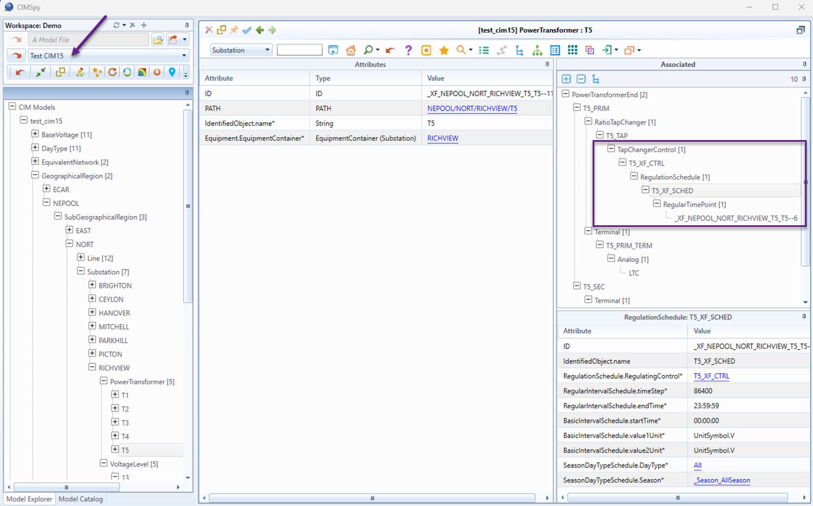
As highlighted in the sample, non-descendant CIM objects such as TapChangeControl, RegulationSchedule, and RegularTimePoints are also included as part of the PowerTransformer. This demonstrates how Custom MVVM allows users to extend model relationships beyond the default hierarchy, enabling a more comprehensive and user-specific representation of the data.
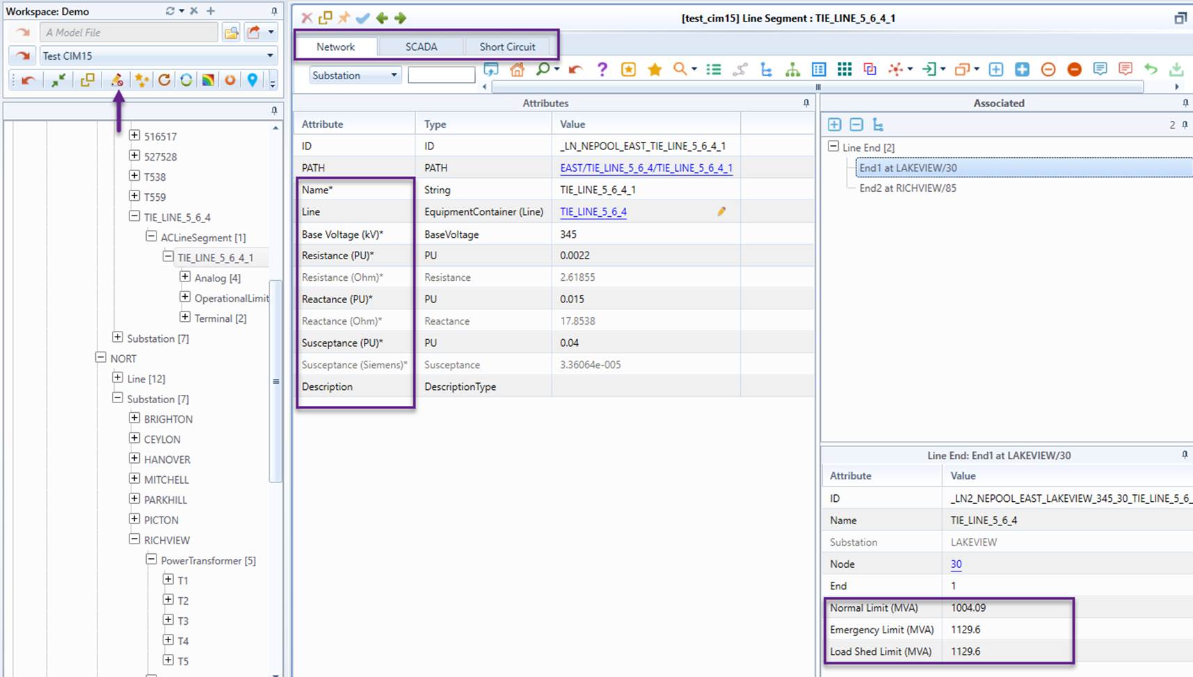
The second sample demonstrates how an ACLineSegment can be presented in a user-friendly form. As shown in the Form:
- The ACLineSegment is presented as different views, including Network, SCADA, Short Circuit, enabling role-based workflow. For example, SCADA-related modeling entries can be modified only by modeling engineers assigned to the SCADA modeling role.
- All attributes are labeled in an engineer-friendly manner, eliminating the need for CIM familiarity.
- The line parameters are displayed or entered in per-unit (PU) values, aligning with read-only standard engineering conventions.
- Fine-granular CIM objects, such as Terminal, OperationalLimitSet, and ApparentPowerLimit, are combined and presented as an integrated object called Line End for simplified display and data entry. It also enforces specific modeling constraints, such as limiting a Line End to only three predefined limits: Normal, Emergency, and Load Shed.
This example highlights how Custom MVVM can improve the presentation of complex CIM objects, making them more user-friendly for engineers.
Declaring Custom ViewModel
The sample ViewModel used in the above example can be found at \config\viewmodel\TestCIM15ViewModel.xml.
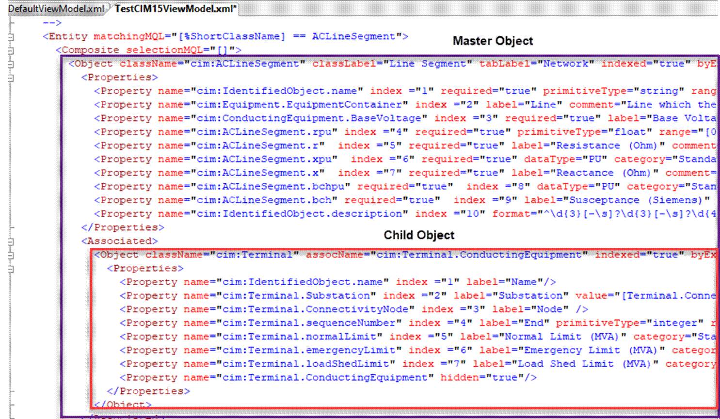
The ViewModel XML definition follows a hierarchical structure, with the elements defined below:
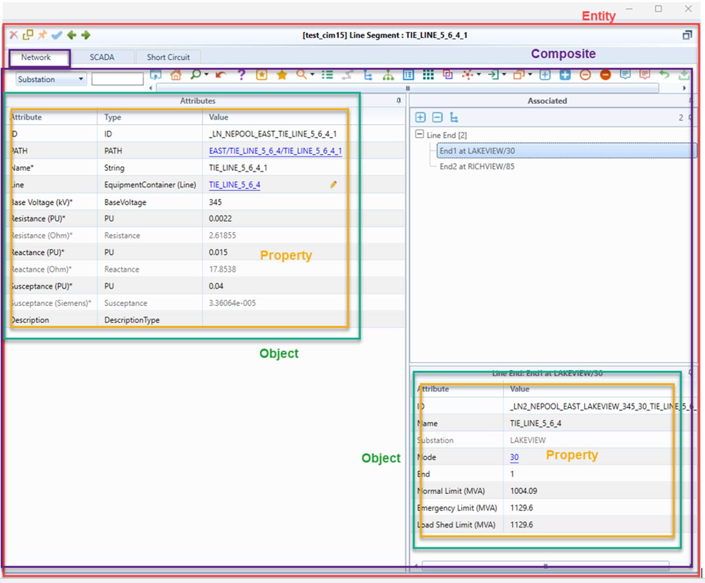
- Entity: An Entity is a single, integrated modeling entity from the perspective of modeling engineers. It is typically composed of a collection of fine-granular, relevant objects. For example, a PowerTransformer Entity consists of objects such as PowerTransformer, PowerTransformerEnd, Terminal, RatioTapChanger, RegulationControl, and RegulatingSchedule. An Entity usually corresponds to a single or multi-tabbed Form display in the UI. An Entity can be created by organizing objects directly from the model or by using a transformed model. In the latter case, a Model-to-ViewModel transformation is required when presenting the model to users, and a ViewModel-to-Model transformation is needed when saving model changes back to the original model.
- Composite: A Composite defines how an Entity is presented in a specific context. For example, it determines how an ACLineSegment and its associated objects are displayed in different contexts such as Network, SCADA, and Short Circuit, each tailored for a specific type of user. In other words, a Composite defines a specific View of an Entity. A Composite typically corresponds to a tab in the Form within the UI. A Composite consists of a master Object.
- Object: An Object defines how an Object from the Model is presented within the context of a Composite. It specifies a collection of properties and a set of associated objects that are relevant to its representation. An Object corresponds to either a Composite Form, if it belongs to a single Composite, or a Tab within the Composite Form, if it is part of a multi-Composite structure Note that Object definition is recursive: an Object contains a collection of associated Objects, each of which may have its own associated Objects, and so on. This recursive structure is presented as navigation tree in the Associated Panel of the Composite Form, allowing users to explore and interact with associated objects in a structured and intuitive manner.
- Property: A Property defines how a property of an object is presented to users in a Composite Form. It can be either a native property from the Model or an extended property from the ViewModel. If it is a native property, the presentation is based on raw or customized meta-information from the Model or Profile. If it is an extended property, relevant meta-information must be provided to guide how the UI displays and handles the property.
The following illustrates how the elements above are presented in a Composite Form.
The attributes of each element are listed in the following table.
Element
Attribute
Data Type
Description
Entity
matchingMQL
string
MQL used to test whether an Entity shall be populated for a given object in the Model.
versions
string
All versions of CIM that the view model is applicable, separated by ';'. If empty, applied to all versions.
applicableMode
int
A (bit) mode that the Object is applicable to a certain type of UI display: all = 0, form_display = 1, popup = 2
Composite
selectionMQL
string
MQL used to select the root object from the Model. The value of “[]” means the Entity object itself. If this value is equal to 'Inferred', Objects will be Inferred.
includeDeclaredChildOnly
bool
If true, only declared children are included during inference of associated objects. applicable only when selectionMQL = 'Inferred'. However, during object editing, only declared children are included even this attribute is set to false. This is essentialto properly support cascading deletion and deep-copy.
maxDepth
int
The max depth during inference of associated objects. applicable only when selectionMQL = 'Inferred'.
maxObject
int
The max number of object that can be serialized to avoid performance penalty, applicable only when selectionMQL = 'Inferred'.
maxEnum
int
The max number of enumerated reference objects that can be serialized to avoid performance penalty, applicable only when selectionMQL = 'Inferred'.
Object
basedOnTemplate
string
If specified, the Object is derived from the referenced Object template.
className
string
Full class name, including namespace prefix.
selectionMQL
string
MQL for selecting the objects from the Model.
assocName
string
Name of the association from child to parent, an alternative to selectionMQL for generating Objects.
refName
string
Name of the association, applicable for none-child/parent associated object, an alternative to selectionMQL for generating Objects.
classLabel
string
Label of the class to be displayed in UI. If missing, className will be displayed.
tabLabel
string
Label for Tab, only applicable for root modeling Object.
objectLabelMQL
string
MQL used to generate label of the object to be displayed in UI.
byException
bool
If false, only specified properties will be populated, otherwise all of the properties undefined will be auto-populated.
indexed
bool
If true, properties shall be indexed, meaning their position are specified in Properties.
contextual
bool
If true, this Object is context-dependent and a specialized template is needed to guide data entry. if not if not specified, we will infer it based on the following rule: contextual is true if selectionMQL is specified or at least one of the properties depends on the context.
minOccurs
int
Minimum number of associated objects, -1 means unrestricted; used for data entry validation.
maxOccurs
int
Maximum number of associated objects, -1 means unrestricted; used for data entry validation.
Property
name
string
Full property name, including namespace prefix.
hidden
bool
Flag indicating whether to hide this property.
initialValue
string
MQL for setting the initial property value, used to set the default value if missing
value
string
MQL for setting the property value, used to populate the dummy property (normally for display-only).
enumObjectSelectionMQL
string
MQL for getting objects that can be used to generate enum values, applicable when displaying association as enum (so that it can be set using dropdown).
enumObjectSelectionMQLFromParent
string
MQL for getting objects that can be used to generate enum values , applicable only when displaying association as contextual enum where the enumerated values are dynamically determined.
enumValueMQL
string
MQL for creating enum values from the objects selected, applicable when display association as enum (so that it can be set using dropdown).
type
string
Type of the property, i.e. attribute, enumeration, or association, meaningful only when value is specified.
index
int
Index of the property displayed in UI, used to set the property display sequence, meaningful only when Object.indexed is true.
label
string
Label of the property displayed in UI. If not specified, name will be displayed.
comment
string
Comment used to describe the property, displayed as tooltip in the UI.
category
string
Category of the property, such as Undeclared, Extended, Standard, used for highlighting.
readOnly
bool
Flag indicating whether this is a read-only property.
dataType
string
Data type of the property to be displayed in UI, such as Float, String, normally from Profile.
dataTypeDesc
string
Description of data type, displayed as tooltip in the UI, normally from Profile.
restrictedClasses
string
Restricted classes, a list of class names separated by ';'. Only objects of the specified classes can serve as the association. Applied to association data types only.
primitiveType
string
Primitive data type, such as string, integer, float
required
bool
Flag indicating whether the property value must be provided
range
string
Range of the value in the format, such as [min, max), used for data entry validation.
format
string
Data format, such as %5.2F or email format in Regex ^[\w\-]+@[\w\-]+\\w{2,}$ , used for data entry validation.
EnumeratedValue/value/uiValue
Element
Customized enumerated values, specified as a sequence of XML Elements with two string attributes, i.e. value: the identifier of the enumeration; uiValue: the corresponding values to be displayed in the UI (needed only if different from value ), only applied to enumeration data types or attributes with enumerated values
Template
Custom ViewModel supports Object templates, allowing complex data sets to be decomposed into smaller, reusable data sets and making it easier to define and manage custom ViewModels.
The following illustrates how an Object template is defined and referenced in the sample TestCIM15ViewModel.xml.
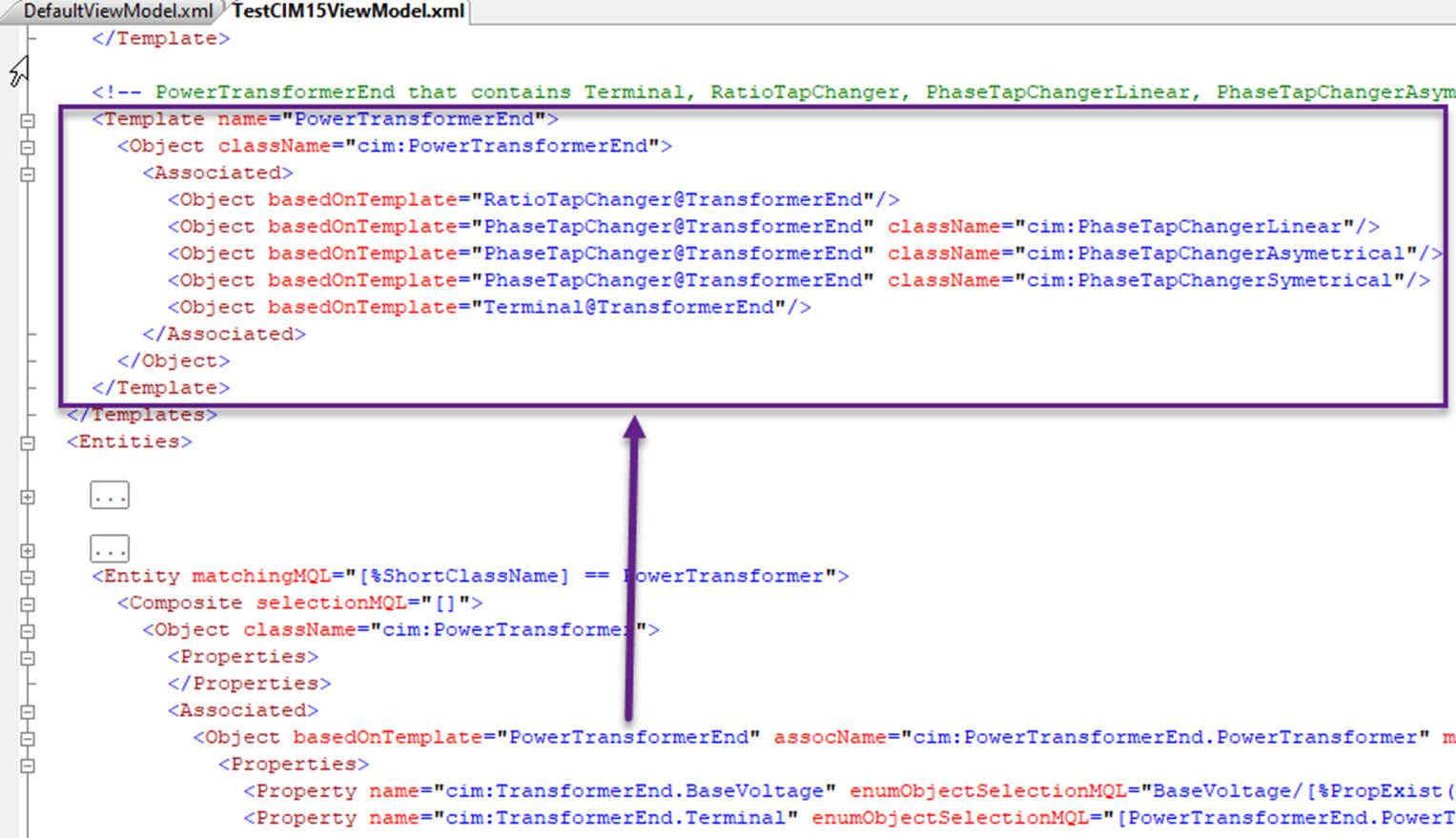
Note:
- An Object template is defined in the same way as an Object.
- Object template is recursive, meaning one Object template can be defined using other Object templates. This allows for modular and hierarchical structuring of data, where reusable templates can be nested to build more complex representations.
- The contents of an Object template can be overloaded by defining the same contents within the Object.
The major benefits of using an Object template include:
- Simplifying the definition of a Custom ViewModel – By decomposing complex data sets into smaller, manageable ones, templates make it easier to structure and define ViewModels efficiently. This modular approach allows for better organization and reuse of data components.
- Reducing redundancy and duplication – Instead of defining the same structure multiple times, templates allow for a single definition to be referenced across multiple instances. This reduces repetitive work, ensures consistency, and simplifies maintenance by centralizing modifications in one place.
- Enhancing maintainability and scalability – Changes made to a template are automatically applied to all instances that reference it, reducing the effort required for updates and ensuring uniformity across the application.
- Providing flexibility through customization – While templates provide a standard structure, they can be extended or overridden for specific use cases, allowing customization without losing consistency.
Transformation
If the Objects defined in the ViewModel are not directly from the raw Model but require processing before being presented to users, a partial model transformation must be declared. This transformation defines how data from the Model is converted into a structured format suitable for the ViewModel. It ensures that relevant information is extracted, formatted, or combined appropriately before being displayed in the UI.
The following illustrates how an ACLineSegement is transformed to a user-friendly Object, where
- The line parameters are converted to the per-unit (PU) values.
- ApparentPowerLimits are combined with Terminal and presented as an integrated object called Line End. for simplified display and data entry.
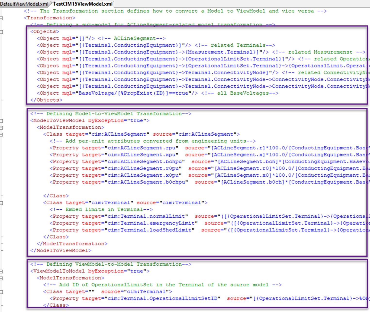
Model Transformation Framework (MTF) is leveraged to achieve partial model transformation. The declaration consists of 3 sections, as highlighted above and described below:
- Object Selection – Defines how a partial model is extracted from the Model. This partial model contains all necessary information required for transformation.
- Model-to-ViewModel Transformation – Specifies how the partial model extracted from the Model is converted into the ViewModel. This transformation structures the data for presentation in the UI, making it more intuitive and user-friendly.
- ViewModel-to-Model Transformation – Defines how the ViewModel is converted back into the Model. This reverse transformation ensures that any Objects created or edited in the UI are properly saved and integrated into the original Model.
Configuration
There are two ways to apply a defined Custom ViewModel to the Model via configuration:
- Applying to a Specific Model – This is done through the configuration of the Data Source as illustrated below, allowing the Custom ViewModel to be applied only to a designated model. This method is useful when different models require distinct ViewModel configurations.

- Applying to All Models in a Workspace – This is achieved through the configuration of the Workspace as illustrated below , ensuring that the Custom ViewModel is applied to all models loaded within the workspace. This approach is beneficial for maintaining consistency across multiple models used in the same environment.
