Template-Based Modeling
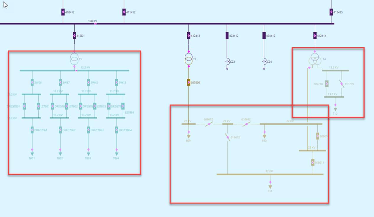
In addition to supporting the basic modeling requirements, the graphical model editor provides an advanced feature, i.e. template-based modeling, enabling users to rapidly build/maintain the network model by using the existing modeling entities as templates. This is based on the fact that a power system typically contains many identical equipment and configurations. The template-based modeling greatly reduces model maintenance effort. With little effort, users can add a parallel line or duplicate a substation. The requirements of data entry become minimal.
Template-based modeling typically occurs within a single Substation. However if the related network component is between two Substations (lines for example), or if the network components used as templates reside in different Substations, users may need to setup a dual-substation graphical modeling environment.
Two types of template-based modeling approaches are supported to meet different modeling requirements:
Copy-and-Paste
In this approach, users can select a network component (ConnectivityNode or Equipment) as template modeling entity, and then add and connect the copied modeling entity within a Substation or between two Substations. The copied network component contains the exact same modeling entries as the template modeling entity. The only difference is the name and the connections. The connection is reset based on the selected ConnectivityNodes. The following screenshots illustrate how Equipment is created through copy-and-paste.
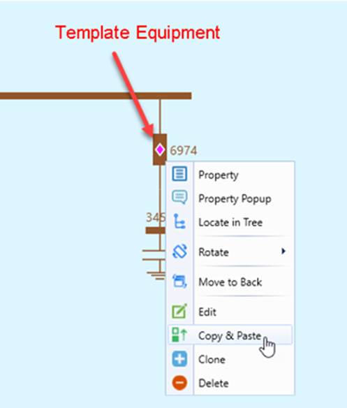
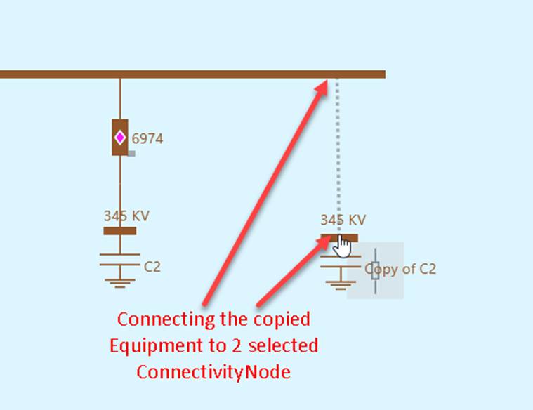
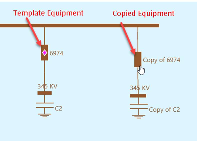
It is important to note that Copy-and-Paste is fundamentally a “shallow-copy” behavior. Although some of the associated connections/container objects (such as Terminals) are copied along with the master equipment objects. In the above example, the (Discrete) measurements (represented as diamond within a breaker) of the template Equipment are not copied. The main reason for not supporting “deep-copy” is to avoid introducing modeling errors. Copy-and-Paste requires users to select the ConnectivityNodes. Multi-terminal Equipment are typically terminal-sensitive. For example, the MW/MVAR measurements of an ACLineSegment are placed at a specific Terminal. When users copy-and-paste a deeply-copied ACLineSegment, the measurements could be pasted to the wrong sides. These kinds of modeling errors are difficult to detect. Therefore, deep-copy is not supported for Copy-and-Paste. If users want to carry all of the related information of the template Equipment, they can clone the Equipment as described below and then reconnect the cloned Equipment to match reality.
Cloning
Cloning is a “deep-copy” behavior. It enables users to duplicate a modeling entity, including Equipment and Substation. A cloned modeling entity is exactly the same as its template, including the topological connections.
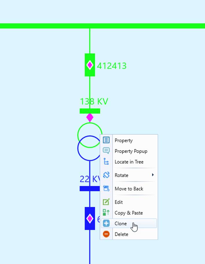
Typically, after Equipment is cloned, the diagram should be redrawn for better clarity.
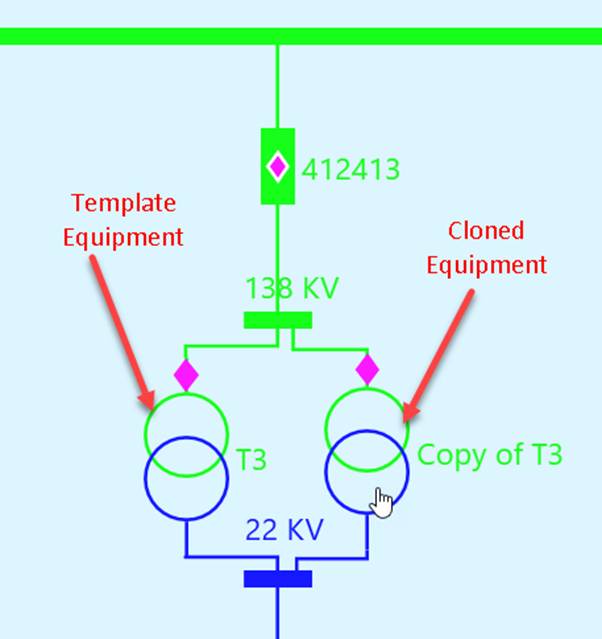
It is important to note that cloning is a deep-copy behavior. When Equipment is cloned, all of its descendent objects, such as Terminals, Measurements, etc., will be copied too. This is the quickest way to duplicate an Equipment modeling entity. After equipment cloning, users may need to re-connect the cloned Equipment to match reality.
Similarly, users can also create a new Substation by cloning from an existing Substation. This is the quickest way to create and initialize the new Substation. A cloned Substation carries all of the information from the template Substation. (Cloning is a deep-copy modeling activity.) It provides users a good starting point for model maintenance if the new Substation to be created is a typical configuration.
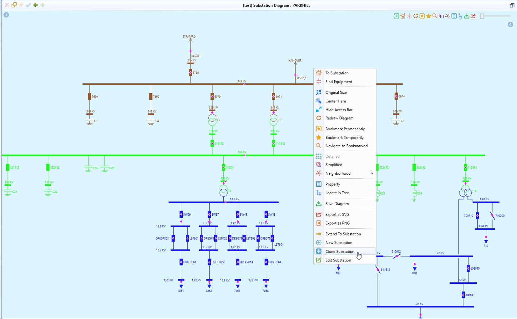
- To create a new Substation by using an existing Substation as a template, users must start with a graphical modeling environment, where typically a detailed Substation Diagram is displayed in the Edit model. Through a context menu, users can invoke the function as illustrated. .
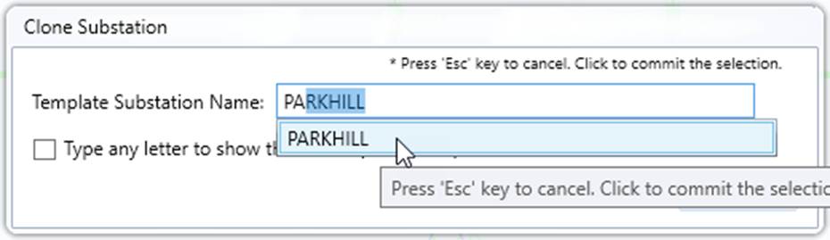
- Search for a Substation that is intended to be used as a template. In this case, we assume the template Substation is the same as the host Substation.
- The cloned Substation will be displayed on the right side in a dual-substation display, as shown below. Note: users may notice that the cloned substation doesn’t look exactly like the template Substation. This is expected. The cloned Substation is an island. It is not connected to other Substations via lines. Transmission lines are not contained in Substation in CIM.
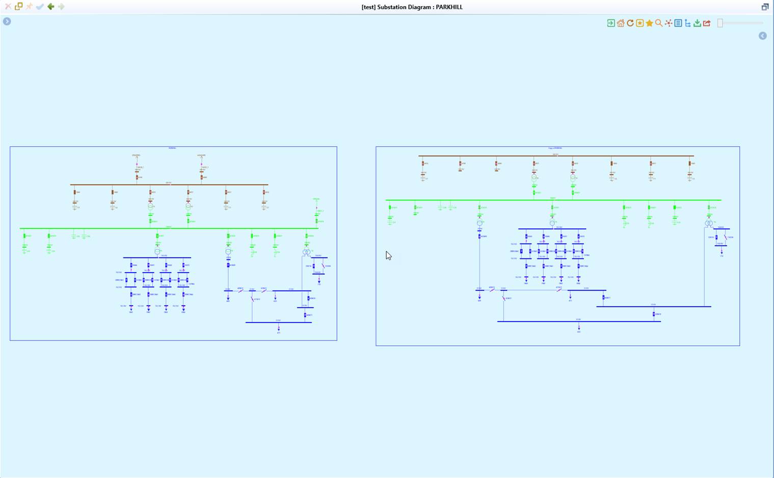
- Start the modeling activities by modifying the newly-added Substation.
Cloning a Group
Interconnected network components can be grouped and cloned as a whole. To do so, users must first group the interconnected network components by using the right-mouse button to drag a group.
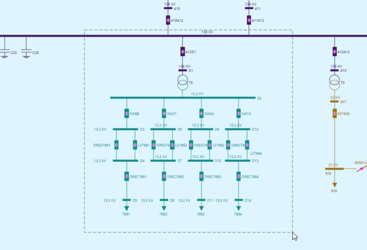
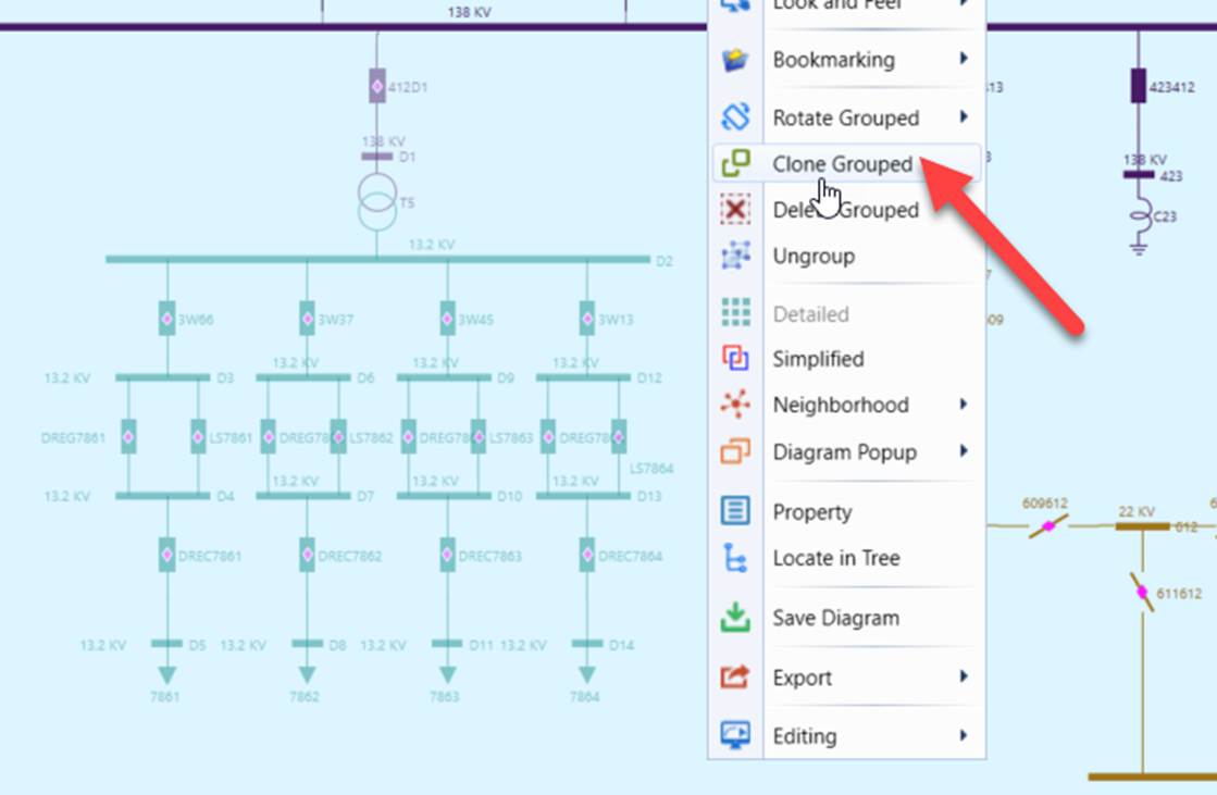
Once the right-mouse button is released, the grouped network components will become grayed. Then click a blank point to invoke the context menu and select “Clone Grouped”.
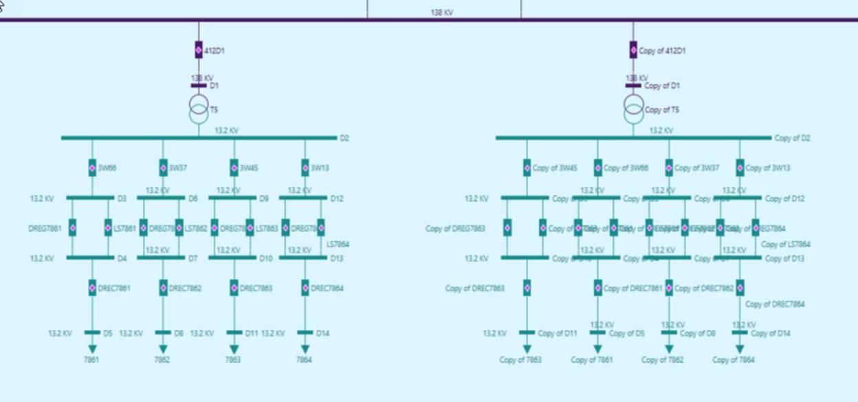
The groped network components will be cloned.
By default, users can select one group for moving/rotation/deletion/cloning. To enable multi-grouping, users must explicitly enable it as one-time effort, as illustrated below.
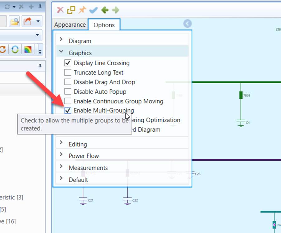
Once enabled, users can select multiple groups (using right mouse) for moving/rotation/deletion/cloning.