Adding and Connecting an Equipment
Equipment is the most common modeling entity users deal with. Equipment modeling entity typically corresponds to a physical equipment in the real world. Equipment is classified as single-terminal and multi-terminal in the graphical modeling environment. A single-terminal Equipment is a shunt with one Terminal object associated, while a multi-terminal Equipment has more than one Terminal associated with it.
In many other graphical modeling tools, adding Equipment typically involves a sequence of graphical modeling activities: dropping equipment and making the connections. The Tool combines these sequential modeling activities into one: adding Equipment by specifying what ConnectivityNodes to be connected. In other words, Equipment can only be dropped on top of or connecting among ConnectivityNodes. The enforced modeling logic minimizes the steps needed for adding new Equipment and ensures that the equipment is always connected. It is believed that users will get used to this modeling practice and prefer it eventually.
Adding and Connecting a Single-Terminal Equipment
- Start with a detailed Substation Diagram and set up the graphical modeling environment.
- Enter the entity-adding mode by selecting the specific modeling entity from the Components Panel or copying from an existing Equipment.
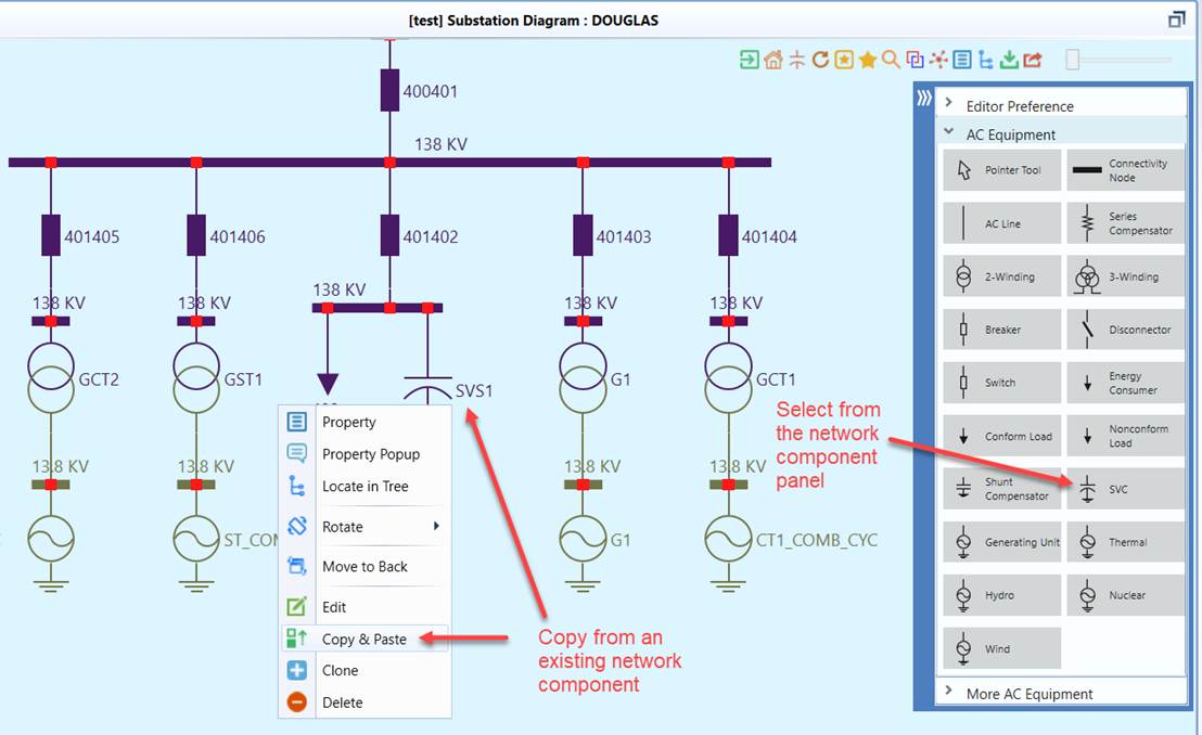
- Move the cursor to the ConnectivityNode where the new single-terminal Equipment is intended to be connected to. If the targeted ConnectivityNode is not available yet. Cancel the operation and add a new ConnectivityNode first. In some cases, user may need resize the length of the buses in order to connect new equipment.
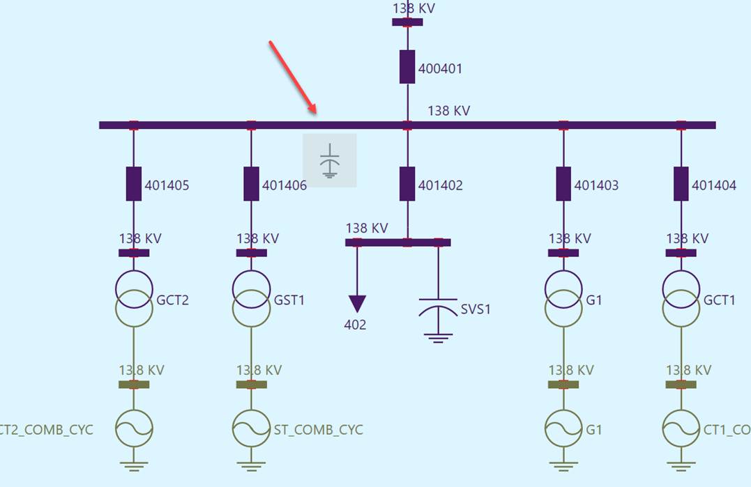
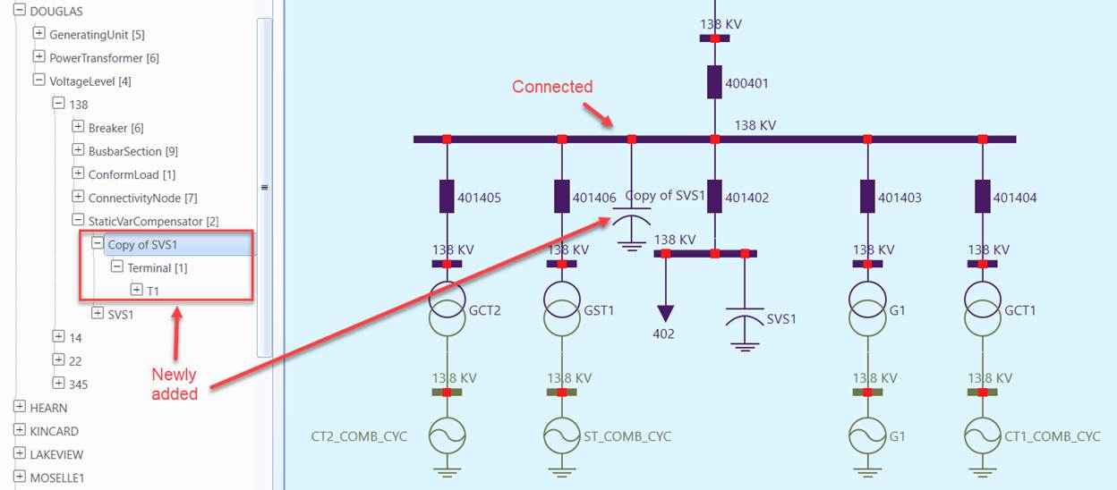
- Click the selected bus symbol, the added/copied new Equipment shall be added to the diagram and the corresponding CIM objects shall be added to the data model, as illustrated below. Furthermore the added single-terminal equipment is connected to the selected ConnectivityNode.
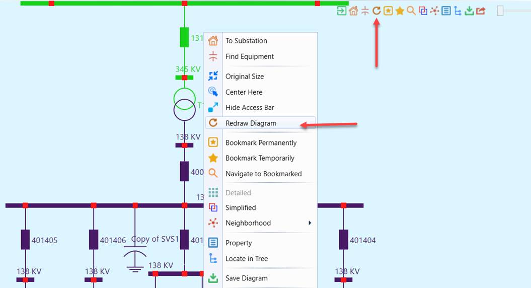
- Optionally, users can refresh/redraw the diagram to allow for the newly added equipment to be optimally laid out. During graphical model editing, the auto-generated Substation Diagrams will be changed, with some network components added and others deleted or reconnected. The resulting diagram may look messy with overlaps occur in different places. This is expected, since the original Substation Diagram is generated based on the network connectivity of the original model. While users can adjust the diagram to adapt to the model changes, a more convenient way is to re-layout the diagram based on the modified model. The following screenshot illustrates how to re-layout the diagram and what the refreshed diagram looks like.
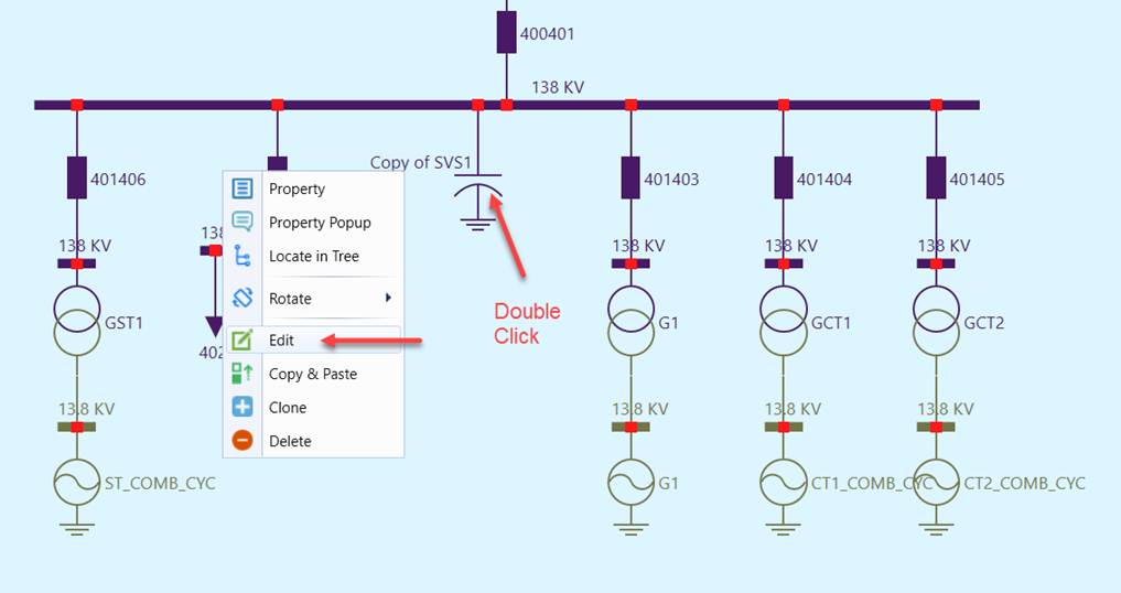
- Optionally, users can edit the newly-added/copied Equipment in the modeling entity popup by double-clicking the new equipment symbol/label or via the context menu associated with the new equipment symbol/label. Click the Save button to commit the model changes.
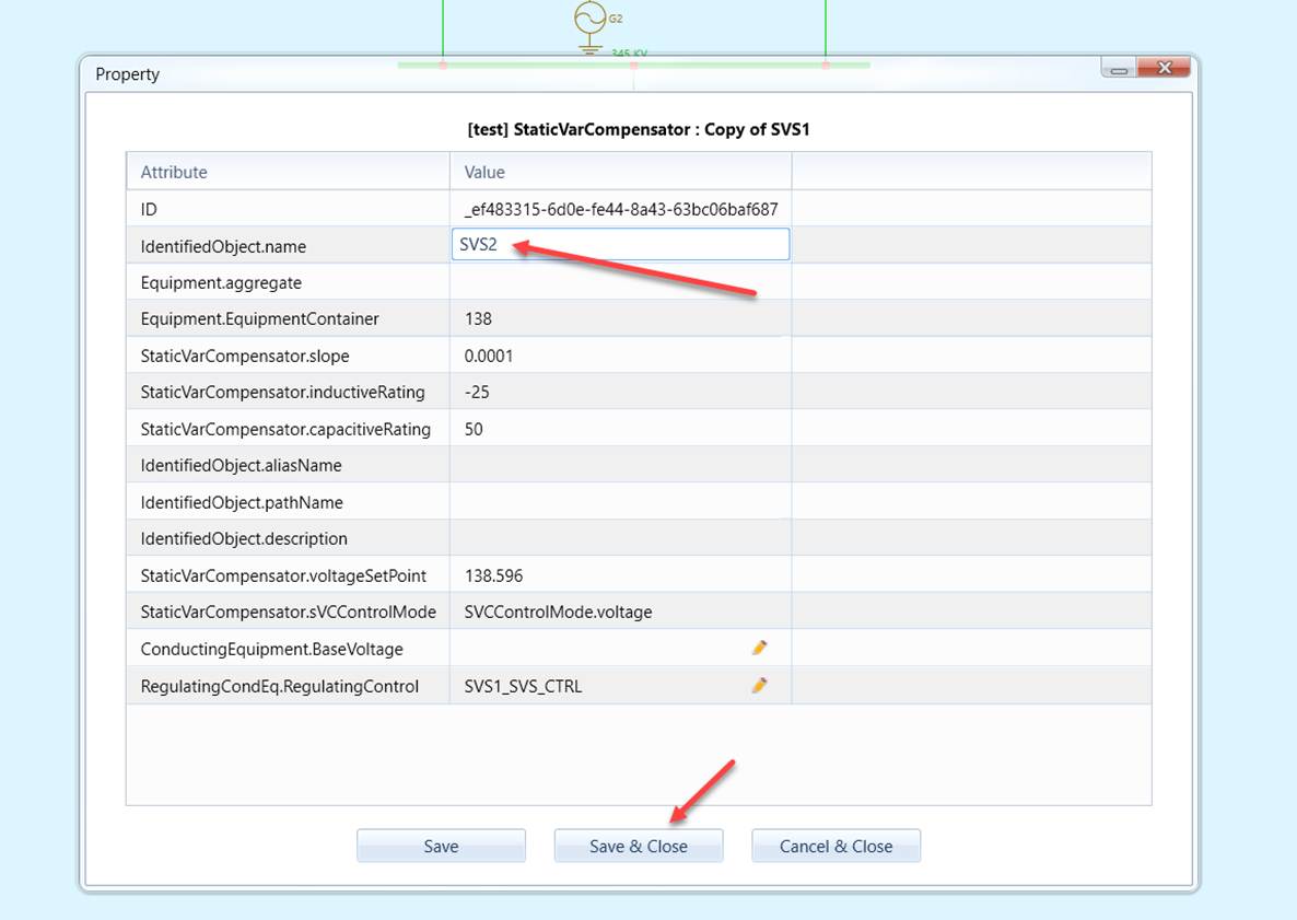
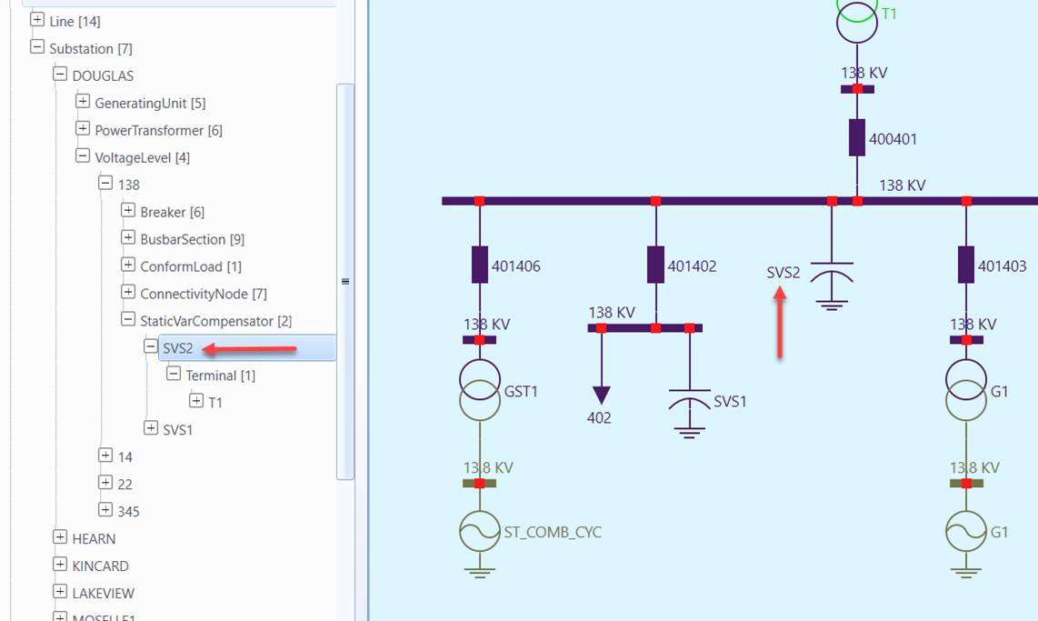
- After the changed property is saved, the diagram and the navigation tree will be automatically updated to reflect the performed model changes. In the above example, the equipment name is changed to SVS2. The label of the edited modeling entity and the corresponding object label in the navigation tree will be automatically updated, as shown below.
Adding and Connecting a Multi-Terminal Equipment
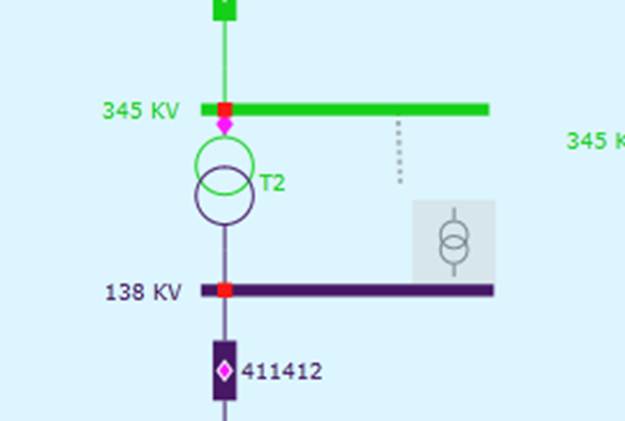
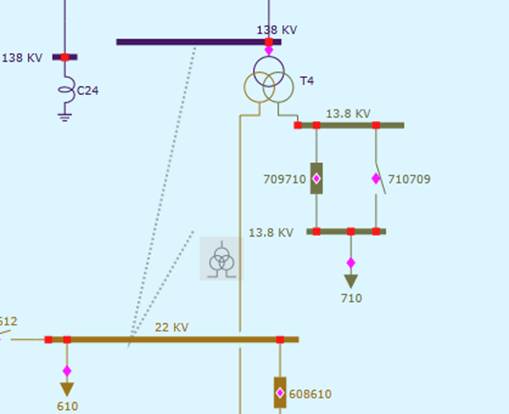
Adding and connecting a multi-terminal equipment is almost identical to adding a single-terminal equipment as described above. The only difference is that users must select two or more ConnectivityNodes in order to drop multi-terminal equipment. For example, users must selected two ConnectivityNodes for connecting an added/copied two-winding transformer and three ConnectivityNodes for connecting an added/copied three-winding transformer as illustrated below. During the node selection, dotted lines appear to follow the cursor movement and trace the ConnectivityNodes being selected.
Adding and Connecting an Equipment between Two Substations
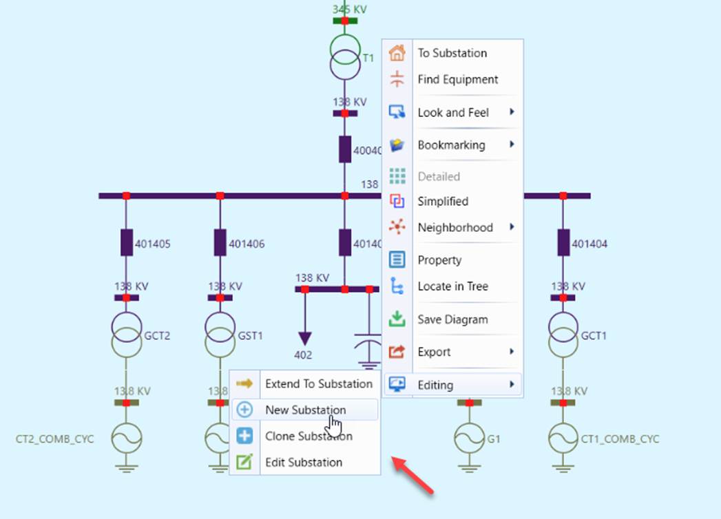
Some Equipment, mainly transmission lines, is between two Substations. Adding and connecting multi-terminal equipment between two Substations requires two Substations to be displayed side-by-side in a dual-substation display. The dual-substation display can be initiated by extending a detailed Substation diagram to include either an existing (i.e. “Extend to Substation”) or an added (i.e. “New Substation”) or a cloned (i.e. “Clone Substation”) Substation, as illustrated below.
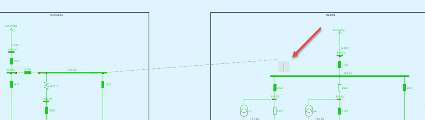
Once two Substations are displayed side-by-side in a dual-substation diagram, users can add one or more Equipment between two substations just like the way adding and connecting a multi-terminal Equipment within a Substation. The following screenshot illustrates how an ACLineSegment is added between two Substations.
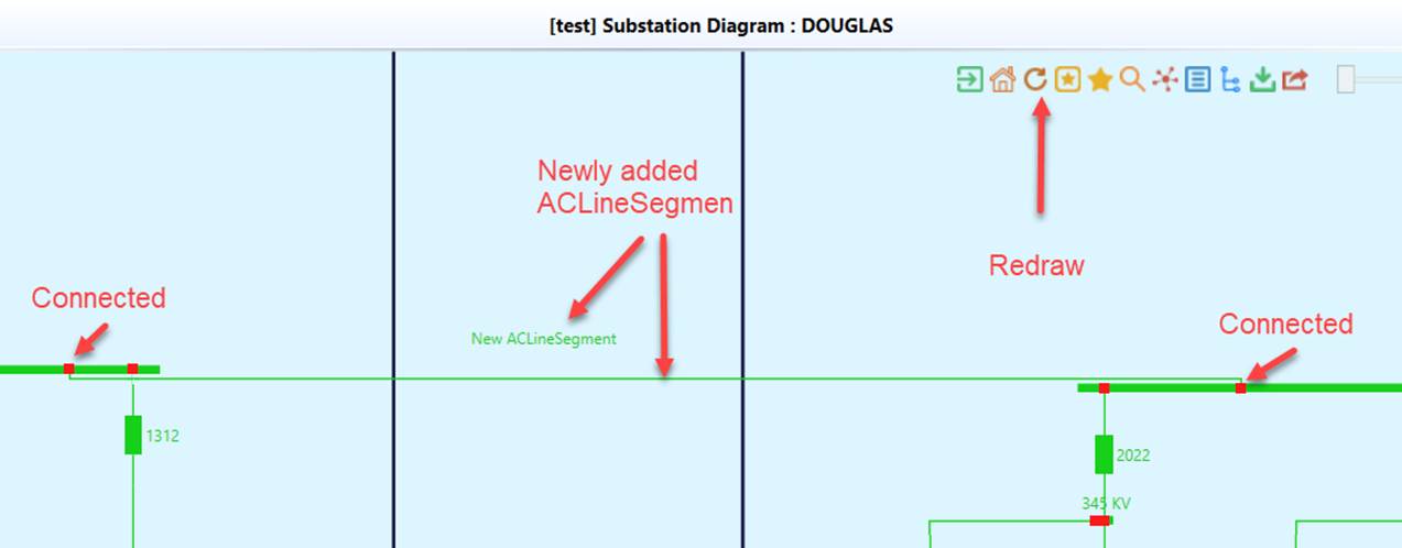
Typically, after Equipment is added between two Substation, the original dual-substation diagram should be redrawn for better clarity.
Cloning an Equipment
The easiest way to add an Equipment to a Substation or between two Substations is through Equipment cloning, a deep-copy modeling activity designed to duplicate a modeling entity. A cloned modeling entity is exactly the same as its template, including the topological connectivity. Equipment cloning is one-mouse-clicking graphical modeling activity, as shown below.
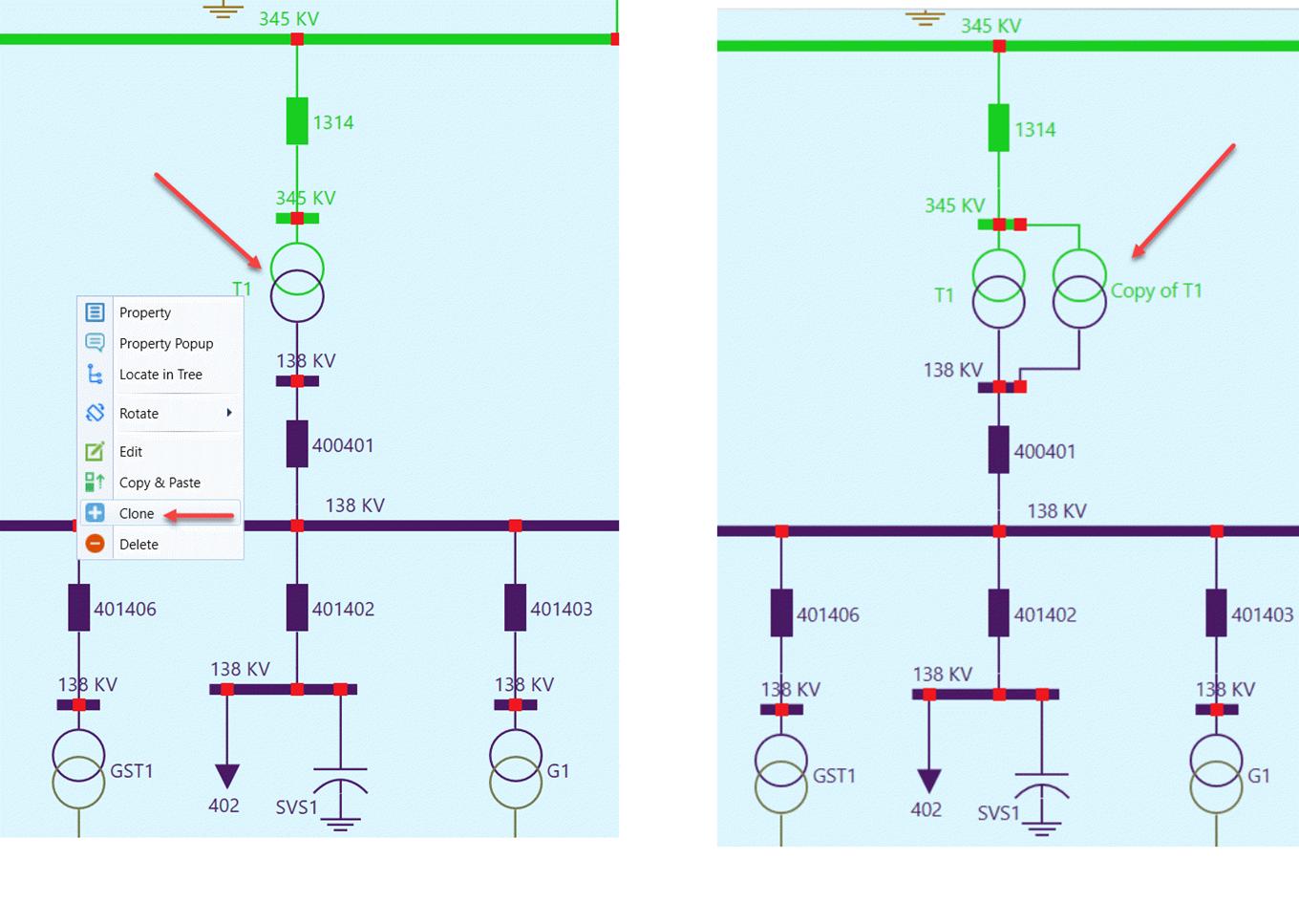
Typically, after Equipment is cloned, the original dual-substation diagram should be redrawn for better clarity.
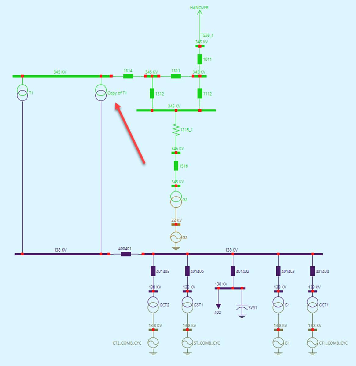
It is important to note that cloning is a deep-copy behavior. When Equipment is cloned, all of its descendent objects, such as Terminals, Measurements, etc., will be copied too. This is the quickest way to duplicate an Equipment modeling entity. After equipment cloning, users may need to re-connect the cloned Equipment to match the reality. Equipment copy-and-paste, however, is fundamentally a shallow-copy behavior. This is because users must select the new ConnectivityNodes for the copied Equipment and a multi-terminal Equipment may be Terminal-sensitive. See Template-Based-Modeling for more detailed explanation.