Case Study 3: Deriving TP from EQ/SSH
This case study is to demonstrate how MTF can be leveraged to support conversion of node/breaker model to bus/branch representation. In CIM, the topology of a node/breaker model is represented using class ConnectivityNode defined in Equipment (EQ) profile, while the bus/branch model is represented using class TopologicalNode defined in Topology (TP) profile. Therefore node/breaker model to bus/branch conversion can be formulated as deriving a TP model from EQ model. However, the switch open/closed status is defined in another profile called Steady-State Hypothesis (SSH) profile. So the TP shall be derived from assembled EQ/SSH in reality. For simplicity, we will use the normal status of the switching devices defined in EQ in this case study.
Hands-on
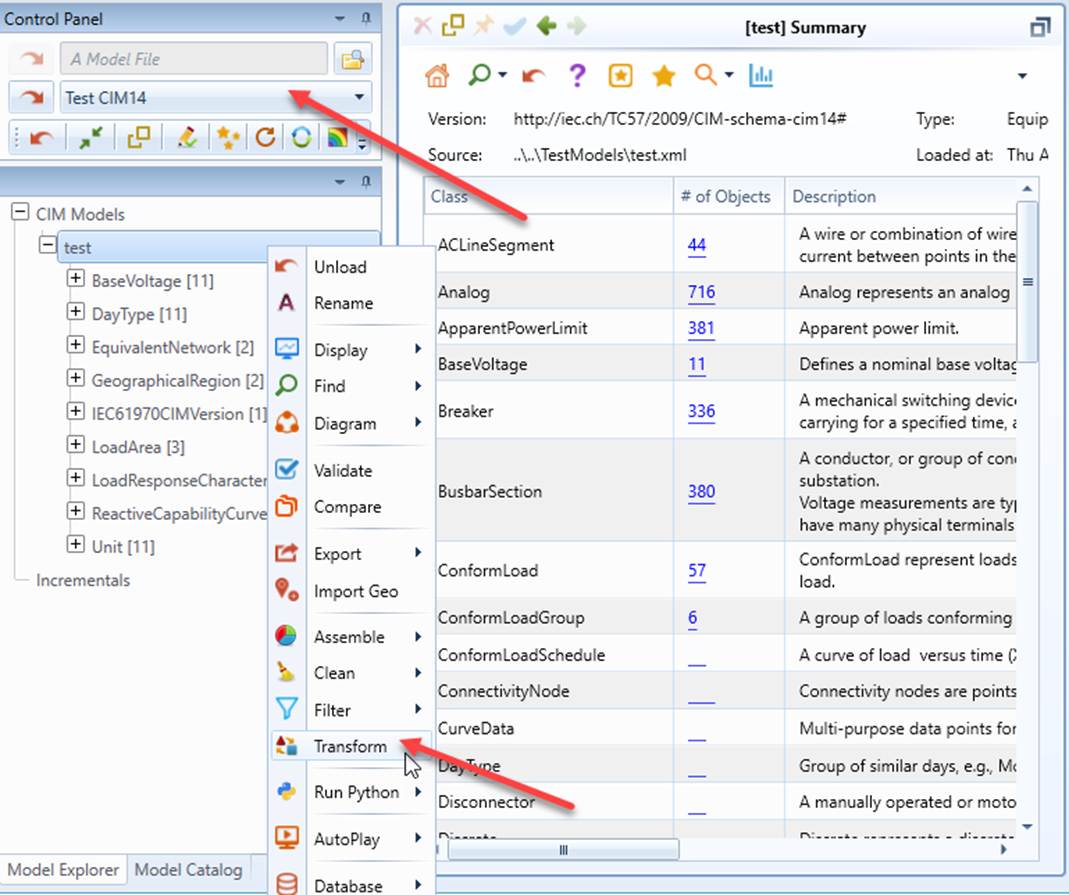
- Load “Test CIM14” from the drop-down list and invoke the Transformation function from the context menu associated with the loaded model.
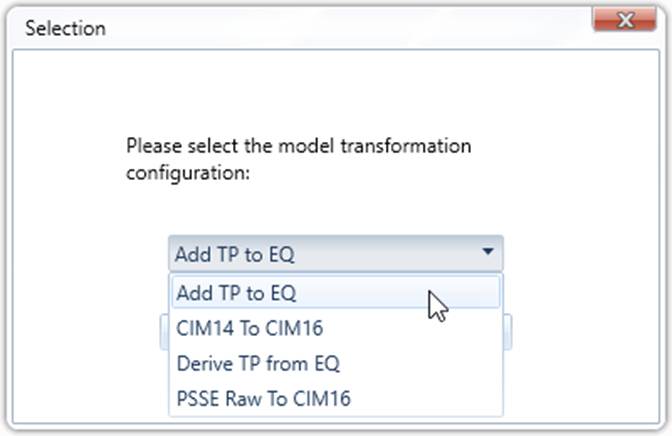
- A popup will appear, displaying all of the transformation configurations defined in the configuration file. There are two configurations related to this case study. Configuration “Add TP to EQ” is used to add TP information directly to the source EQ model. No separate target model will be created. Configuration “Derive TP from EQ” will populate a separate TP target model. Select “Add TP to EQ” from the drop-down list, and then click OK to invoke the model transformation process.
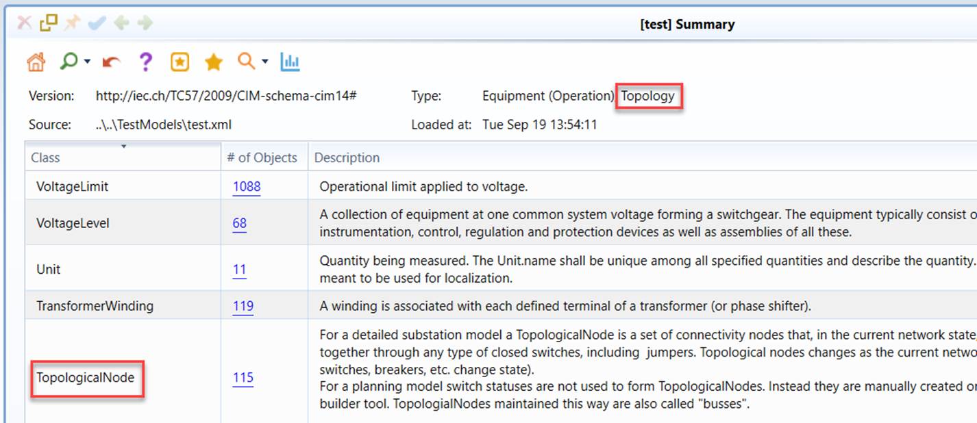
- After the transformation is completed, check whether a new class, called TopologicalNode, is added to the original source model.
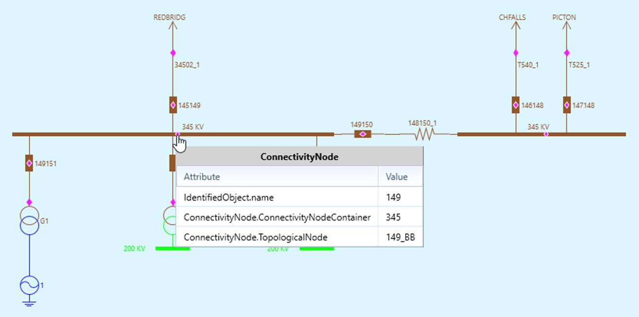
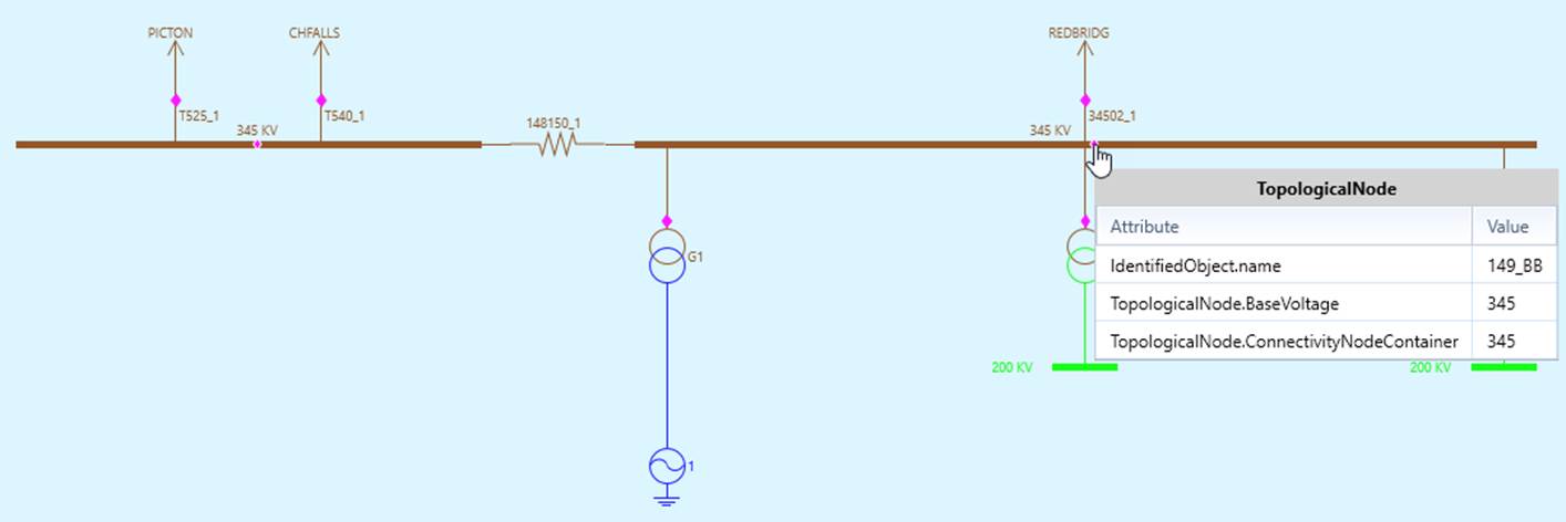
- Call a substation “Detailed” diagram and “Topological” diagram, as illustrated below, to ensure that none-retained switching devices are eliminated and TopologicalNodes are properly created.
Node/breaker representation of a Substation
Converted Bus/Branch diagram of the same station
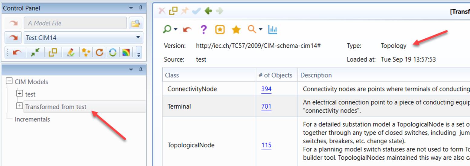
- Repeat process 2 – 4 with “Derive TP from EQ” configuration. In this model transformation, a target TP model will be created, as illustrated below.
In-depth Look
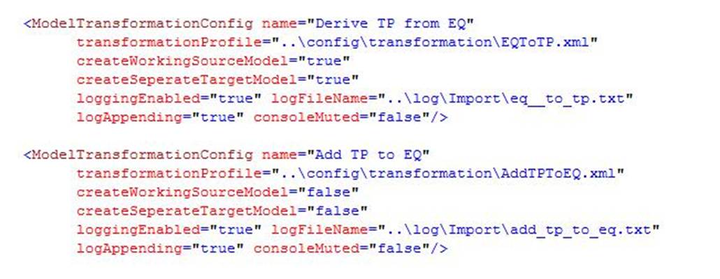
The two model transformation configurations used for node/breaker to bus/branch conversion are shown below. The difference is attribute createSeperateTargetModel, as explained above.
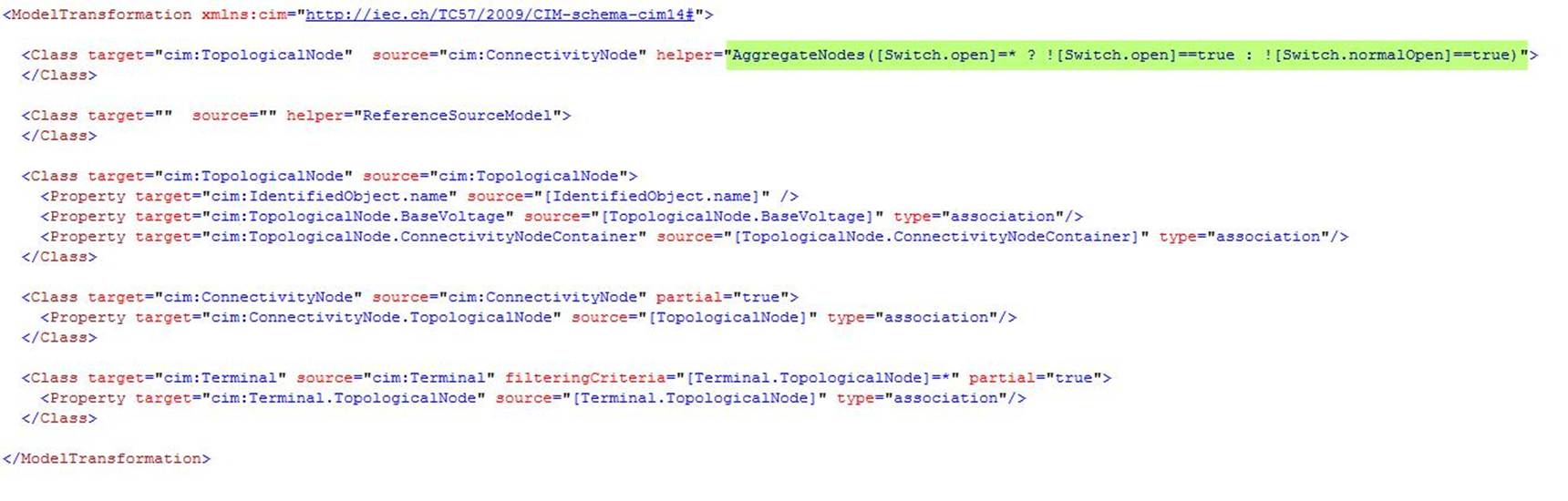
The transformation profile used to derive TP from EQ is shown below. It is quite simple. The key is the helper function AggregateNodes, which groups ConnectivityNodes connected by closed switching devices to form TopologicalNodes. The parameter passed to this function is a MQL logical expression that defines what a “closed” switching device is: if the current open/closed status (from SSH) is available, then use it to determine whether a switching device is closed, otherwise using the normal status (from EQ) of the switching device