Equipment Diagram
Equipment Diagram is aimed to displays the selected equipments and its surrendering network components within a Substation or across two Substations. This feature was designed to support exploratory data analysis, especially helping users find the context information. Equipment Diagram is an extension of Substation Diagram with emphasis on highlighting the selected network components. More specifically:
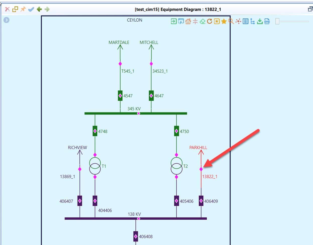
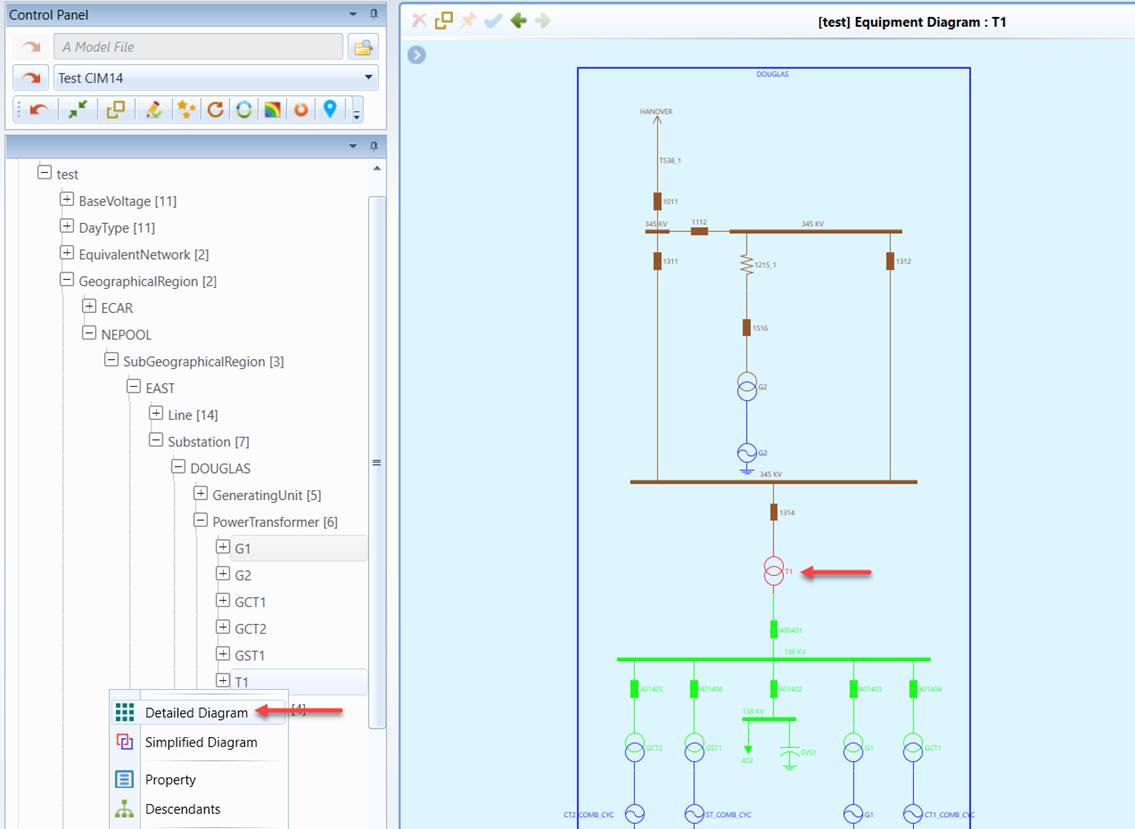
- If the selected equipment is within a substation, the corresponding substation diagram is called with the selected equipment highlighted in red as illustrated the following screenshot.
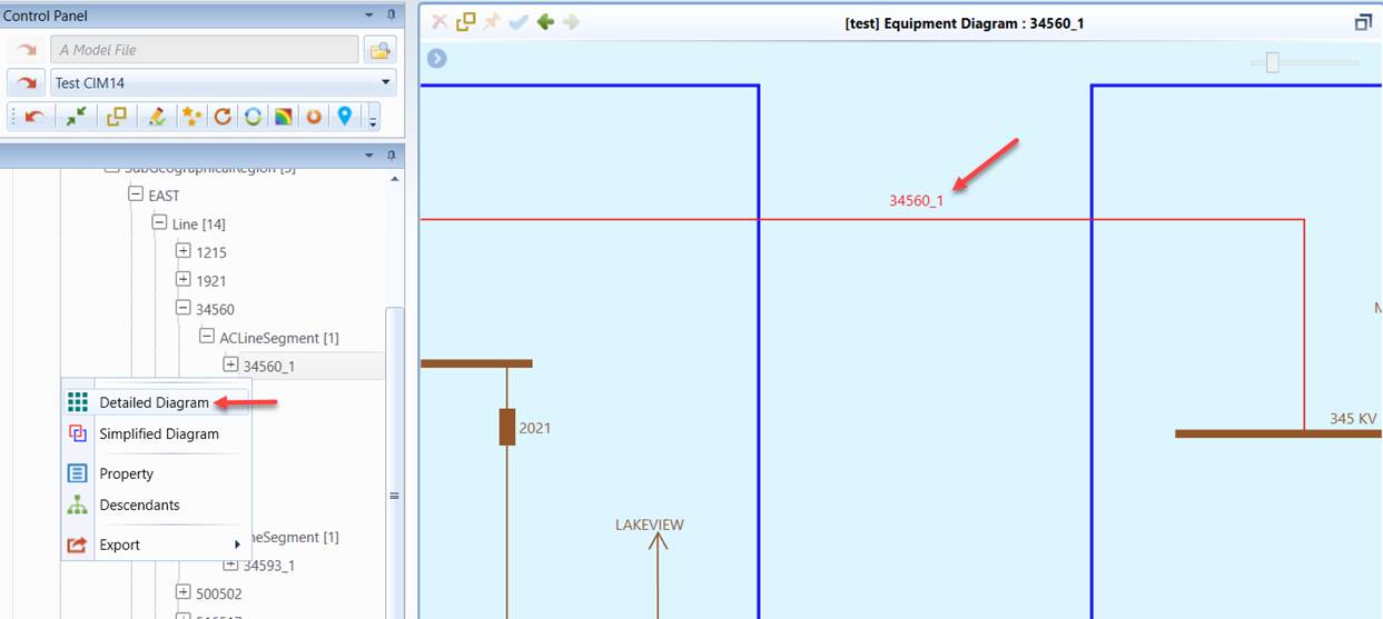
- If the equipment is between two neighboring substations, both substations and the equipment between them are displayed as shown the following screenshot.
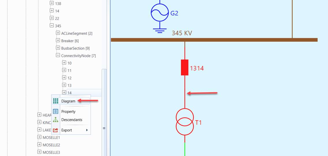
- If the selected network component is not explicitly displayed in the Substation Diagram, the related information will be highlighted instead. For example, ConnectivityNodes or TopologicalNodes are treated as special equipments. Therefore, users can call an equipment diagram for a ConnectivityNode or a TopologicalNode. However not all of these modeling entities are displayed as bus representations in a substation diagram. To pinpoint the location of a selected ConnectivityNode or a TopologicalNode, all of the equipments connected to the selected ConnectivityNode or a TopologicalNode are highlighted, as illustrated in the following screenshot.
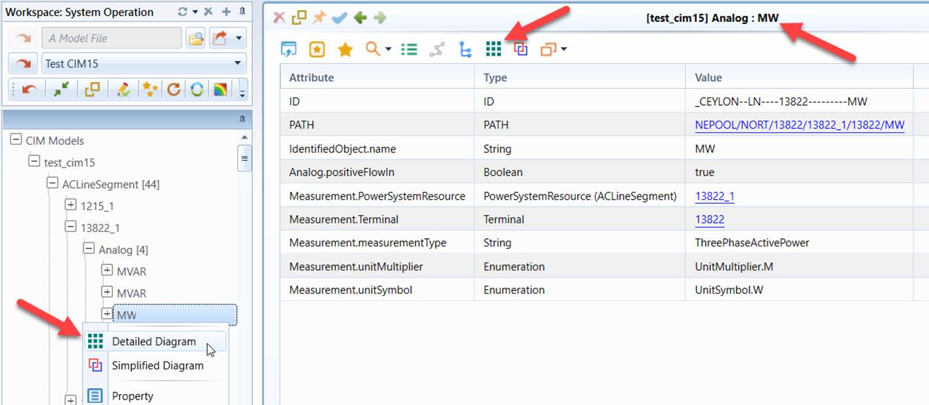
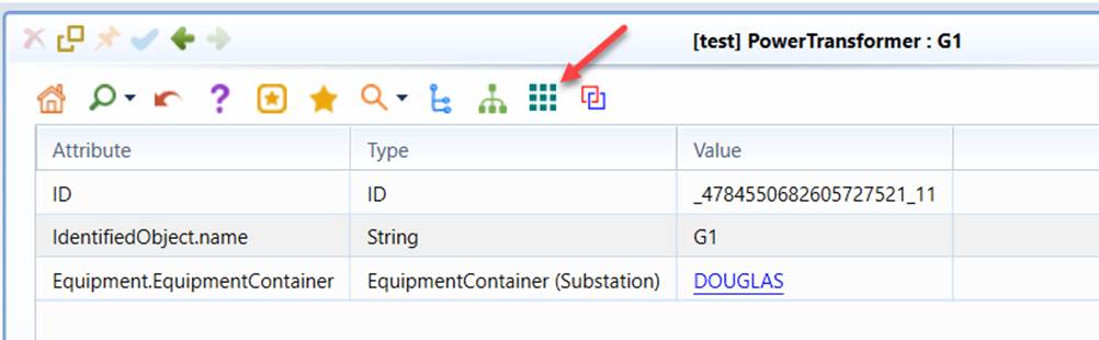
Equipment diagram can also be called from the object Form Display of the selected equipment.
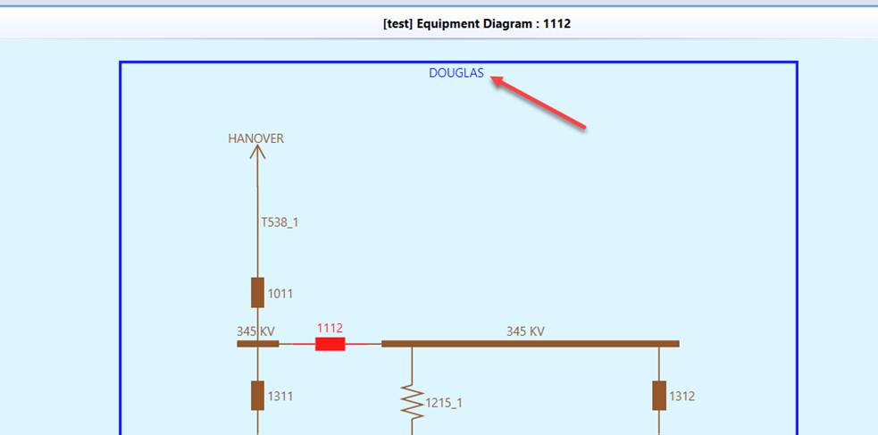
Users can navigate from Equipment Diagram to the Substation Diagram for more activities by double-clicking the Substation name annotation as illustrated in the following screenshot.
Because Measurements (Analog, Discrete, etc.) are associated with Equipments, Equipment Diagrams can also be used to visualize the location of Measurements, as illustrated below.