Reconnecting Network Components
Network reconnection modeling activity is targeted to support the following modeling use cases:
- Network topology has changed. Users want to reconnect some of the existing Equipment to match the reality.
- Users add the new network components and enter the modeling entries. Later they find that the added network components are not correctly connected. They have to correct the network connections.
- Users clone an Equipment or Substation as a starting point and then reconnect the cloned Equipment based on the reality.
Get Prepared
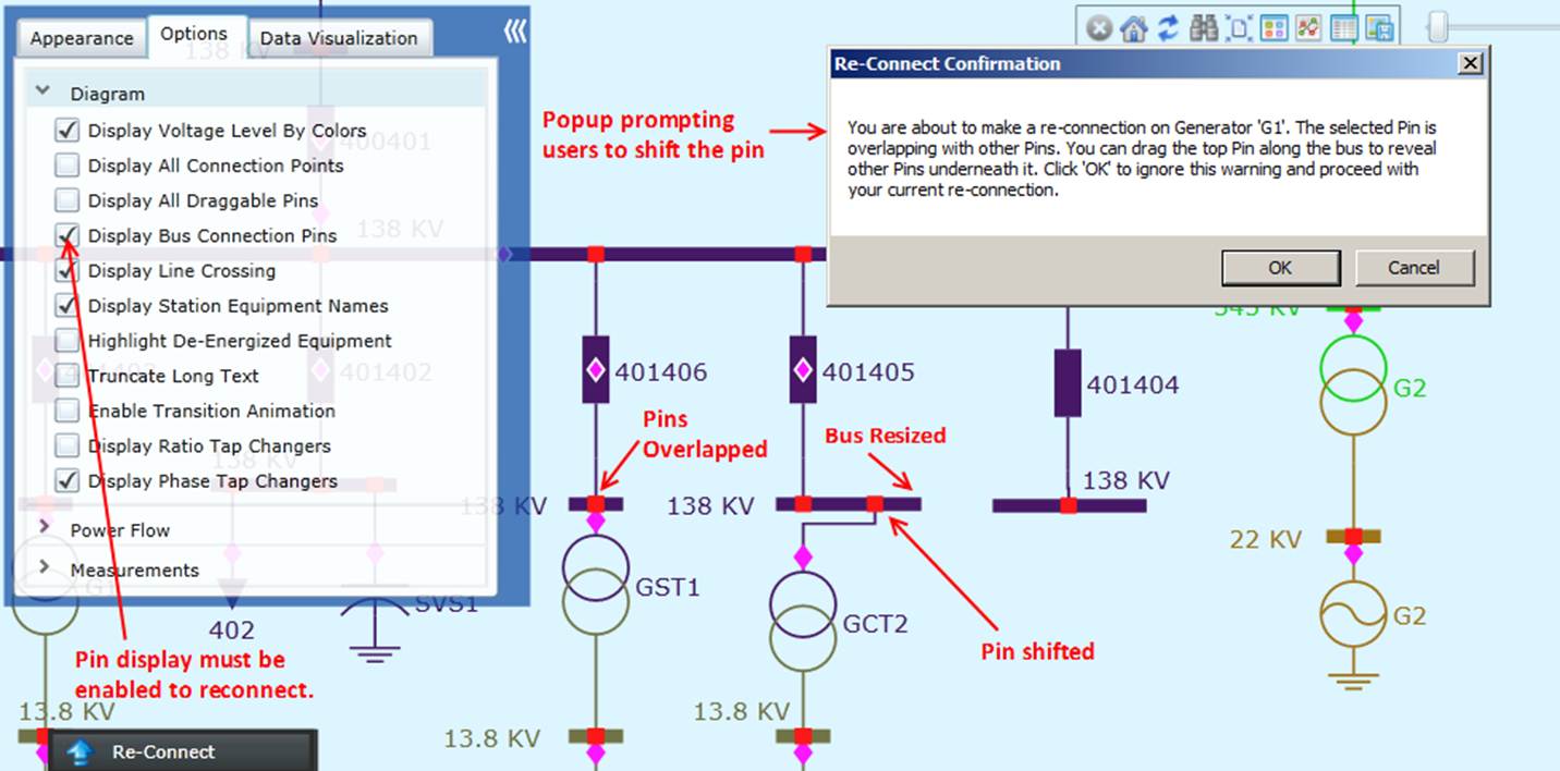
In a detailed Substation Diagram, network connections are highlighted using pins. Naturally, the reconnection modeling activity is performed from a context menu associated with a pin. Pins, however, may be hidden by default. In this case, users must explicitly enable pin display in order to perform the equipment reconnection, as illustrated below. In the cases where pins are overlapped, users will be prompted to shift the overlapped pins so that users can select the right pin to reconnect. In many cases, users also need to resize the buses to perform the network reconnection modeling activity.
Re-Connecting an Equipment
- The reconnection modeling activity is initiated from a context menu associated with a pin, as illustrated.
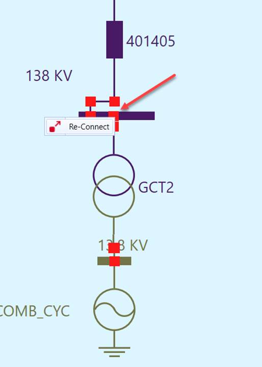
- Once the reconnection modeling activity is invoked, users must select the targeted bus/ConnectivityNode to reconnect the selected pin. Dotted lines are created to follow the cursor movement, allowing users to trace the on-going re-connection, as illustrated below.
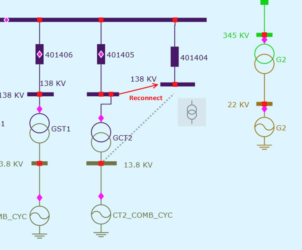
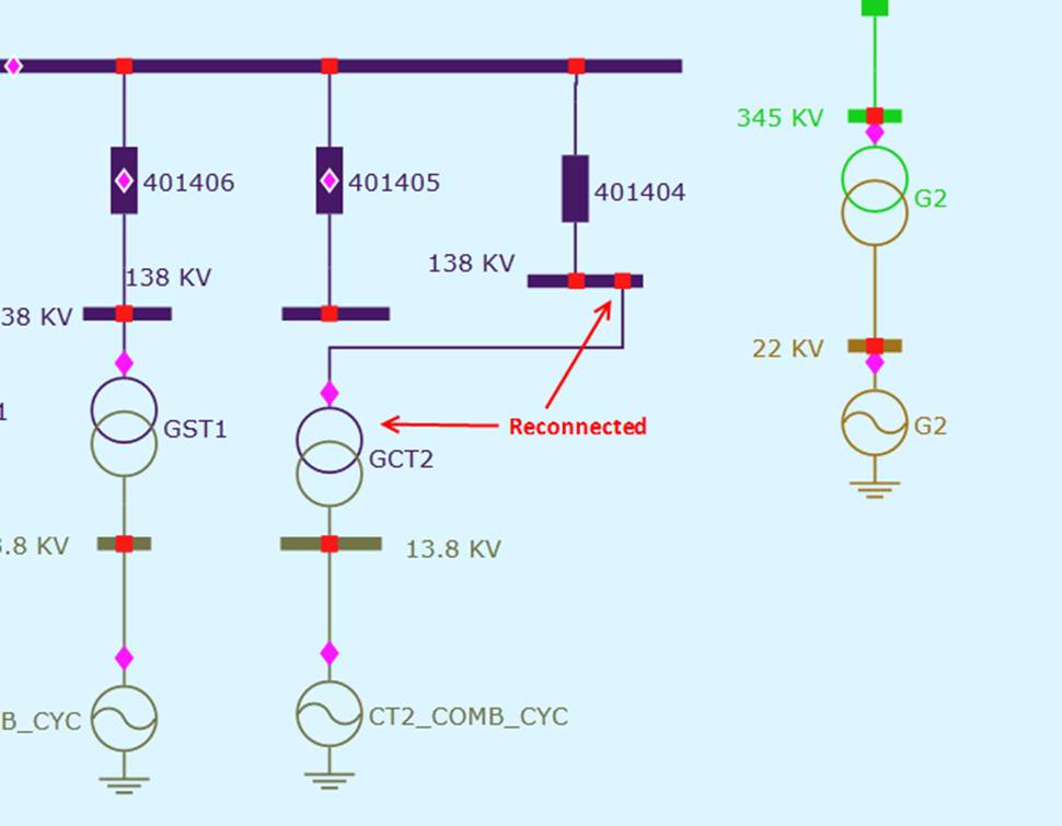
- Re-connected Equipment stays in the original place, even though its connection is re-routed to other bus/ConnectivityNode. While this designed behavior matches common look-and-feel, sometimes the reconnection could result in messy diagram.
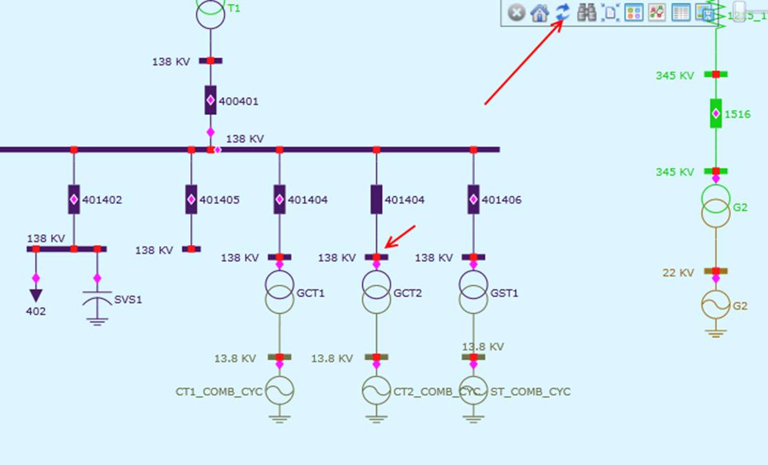
- Optionally, users can refresh/redraw the diagram following equipment reconnection. The original Substation Diagram is based on the network connectivity of the original model. While users can adjust the diagram to adapt to the model changes, a more convenient way is to re-layout the diagram based on the modified model. The following screenshot illustrates what the refreshed diagram looks like for the above example. But a refreshed diagram, sometimes result in the loss of the context.
Model Transplantation
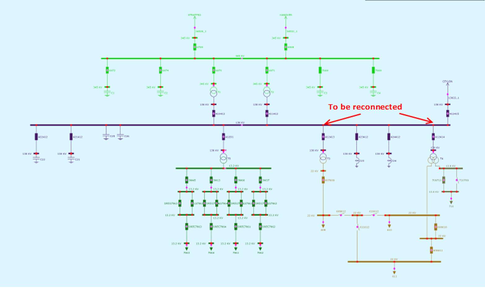
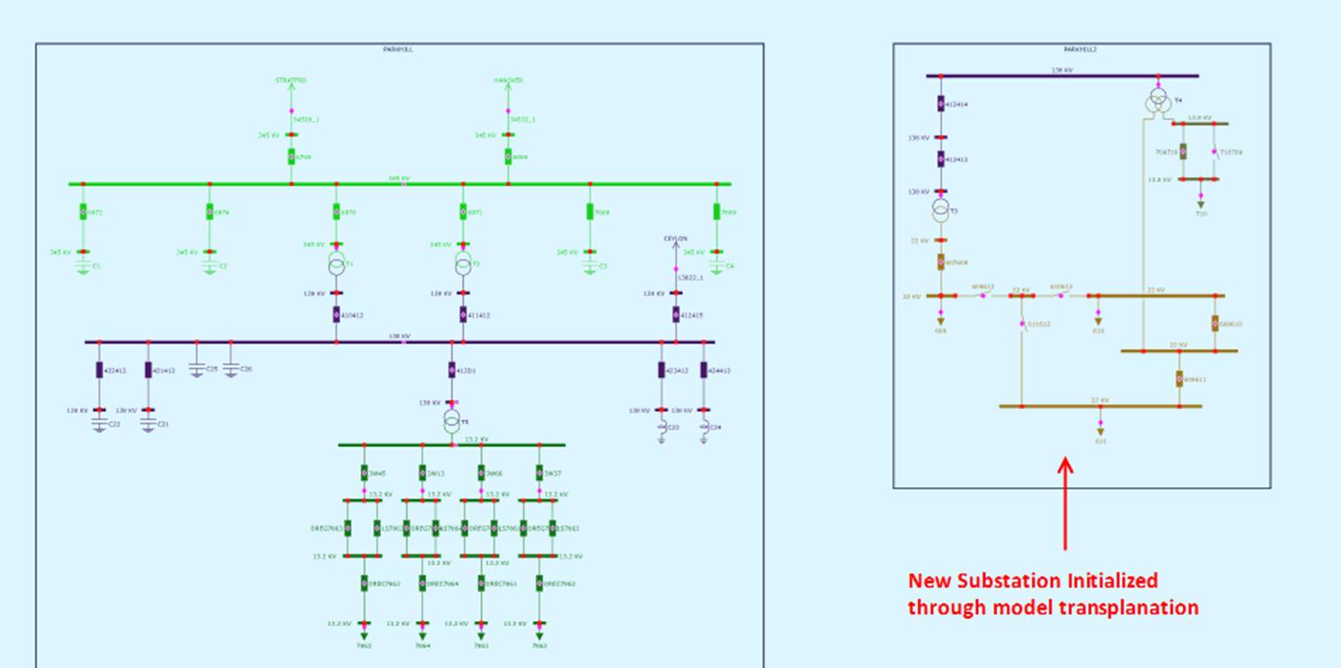
Equipment reconnection typically occurs within a single Substation, except for transmission lines. Model hierarchies typically remain intact. If users reconnect Equipment to a ConnectivityNode contained in a different Substation, it could result in model hierarchy change. The Tool analyzes each reconnection modeling activity and determines whether the containership of the impacted equipment shall be updated. Due to the performed network reconnection, an interconnected portion of the network could be moved from one Substation to the other. This modeling activity is called model transplantation. In some cases, users may want to intentionally split an existing substation jointly owned by two utilities into two logical substations to facilitate model management. The model transplantation will significantly facilitate this substation splitting modeling task. The following screen shots demonstrate how model transplantation is used to spit a single station into two through reconnection. The first screenshot displays the original Substation, while the second displays two split Substation side by side.