Low-Voltage Network Reduction
A transmission network model normally contains some low-voltage (LV) details. These LV details, normally below 110 kV, may not be needed in
- a regional model that are normally assembled with individual models submitted by member utilities;
- an external network model from neighboring utilities or regional coordinators;
- a planning model.
To meet this emerging requirement, the Tool provides a model process function, referred to as LV Network Reduction. This model processing function
- Identifies LV portions of the network based on user-defined rules;
- Removes the identified LV portions of the network;
- Adds equivalent loads/generators at the cut-points;
- Cleans up the reduced network models and marks the points of interest.
Due to the lack of general rules, LV Network Reduction process is highly configurable, enabling users to customize the process to meet their specific needs.
Hands-on
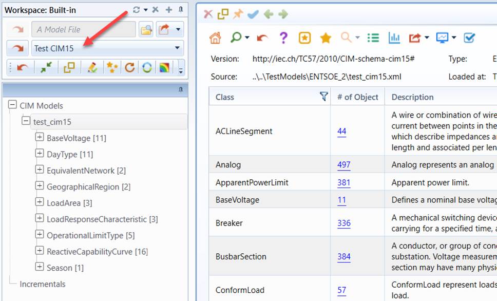
- Load “Test CIM15” from the data source dropdown.
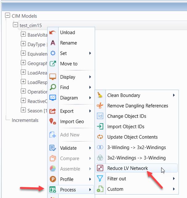
- Invoke LV reduction (Process→Reduce LV Network) from the context menu associated with the loaded model.
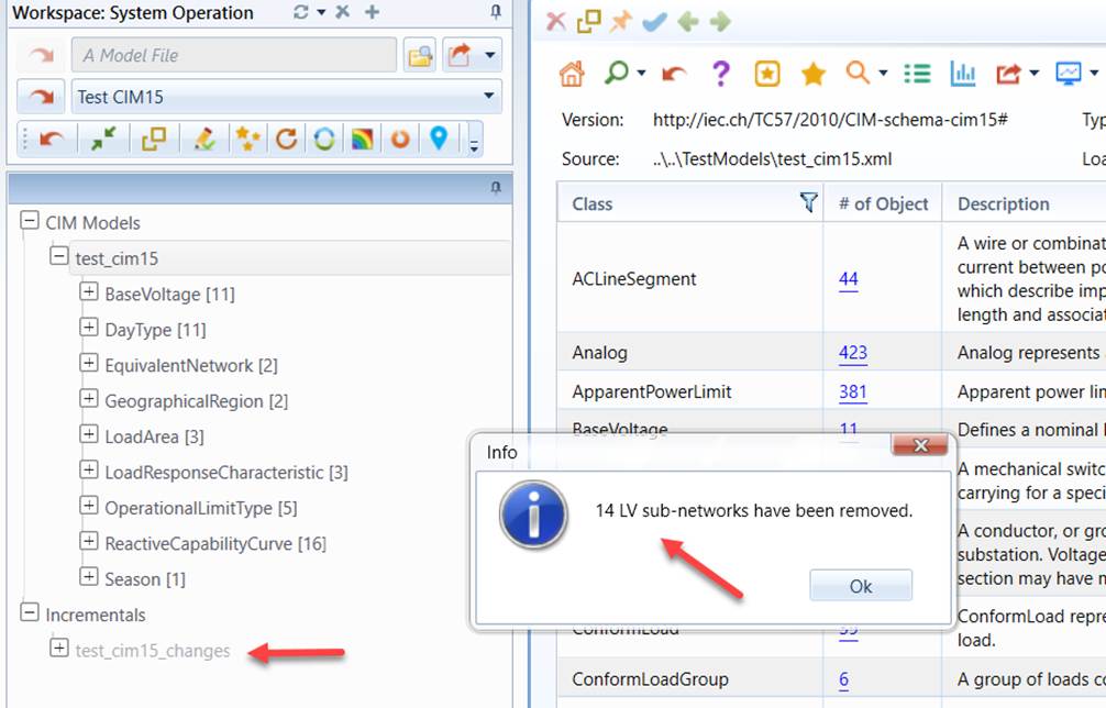
- After the process is completed, users will be prompted, displaying the number of LV sub-networks. A CIM incremental model will be also created, logging model changes
- After LV reduction, the LV details will be removed and replaced with the equivalent loads and generating units, as illustrated below.
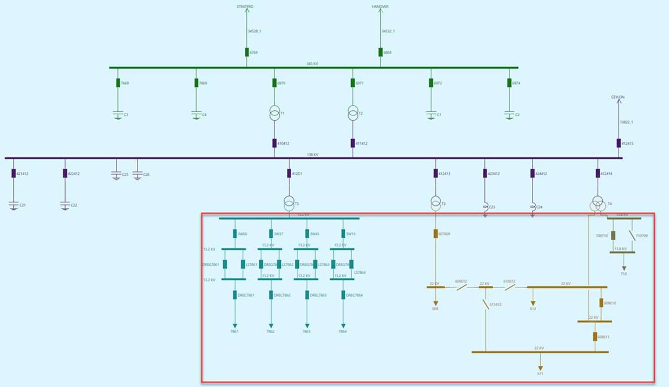
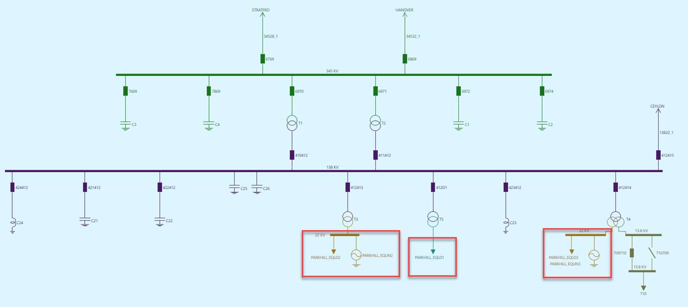
About LV Network Reduction
Low-voltage (LV) portions of networks are connected to high-voltage(HV) portions of network via step-down transformers. If they are cut at either sied of these transformers, multiple LV islands can be created. Each island is referred to as a LV sub-network. If a LV subnetwork is connected to HV through a single transformer, it is called radial LV sub-network. If a LV subnetwork is connected to HV via multiple transformers, it is called loop LV sub-network. The following illustrates a radial LV sub-network vs. a loop LV sub-network.
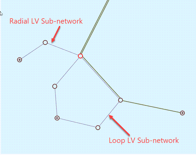
During LV Network Reduction, there are some practical considerations:
- Generators are normally located in these LV sub-networks. The generation LV sub-networks, particularly with large generation, shall not be reduced. These generation LV sub-networks shall be retained.
- The cut-pints shall be located at the low-voltage side of the transformers. In other words, transformers that connect LV with HV shall be retained. This is because these transformers normally carry useful ICCP measurements, which are critical for equivalence.
- After LV sub-networks are removed, equivalent injections shall be added at the cut points for the equivalence purpose. The class of EquivalentInjection was introduced in CIM 15+ for this purpose. However, the concept of EquivalentInjection is not supported by many underlying systems, such as EMS. As an alternative, equivalent loads can be used. For loop LV sub-networks or sub-networks with generation, equivalent generators may also be added along with equivalent loads at the cut points.
- After LV Network Reduction, a post-process may be needed to set some parameters of equivalent loads/generators. For example, set the load parameters based on measurements. This post-process can be manual with recording enabled or automatic by injecting a Python script.
LV Network Reduction Rules
The LV Network Reduction process is governed by a set of configuration settings defined in a CSV file, i.e. \config\custom\lv_reduction\LVReductionSettings.csv. All of the configuration settings are defined as key/value pairs and summarized at the end of this article. Among these settings, the most important are LV network reduction rules, which are used to identify LV sub-networks that need to be removed.
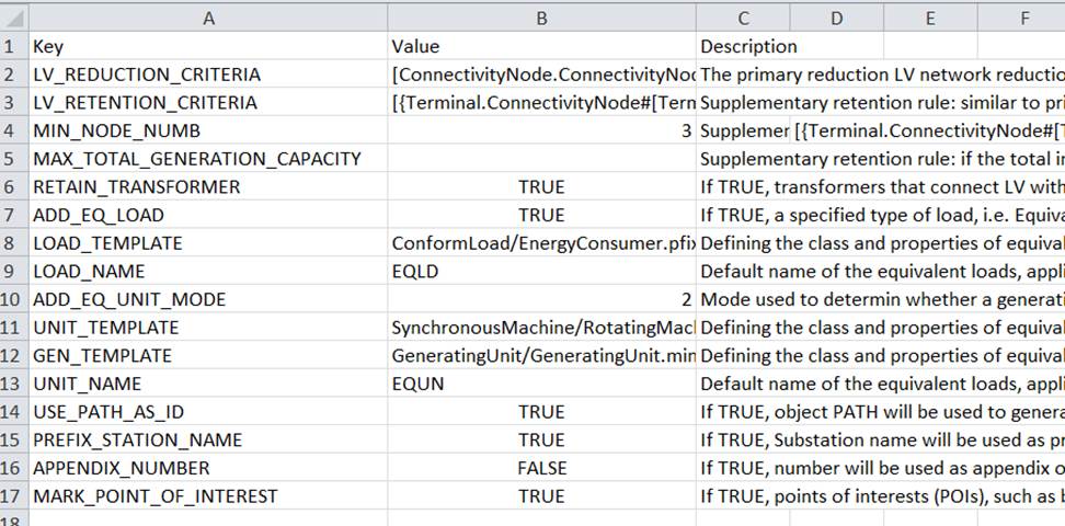
LV network reduction rules contain one primary reduction rule identified by key LV_REDUCTION_CRITERIA and a few supplementary retention rules identified by keys: LV_RETENTION_CRITERIA, MIN_NODE_NUMB, and MAX_TOTAL_GENERATION_CAPACITY. The former is general rule used to identify a set of LV sub-networks that serve as candidates, while the latter are used to refine the LV sub-networks identified by the primary rule. To be qualified for reduction, the LV sub-networks must
- Trigger the required primary reduction rule, AND
- NOT trigger any of the optional supplementary retention rules.
The primary reduction LV_REDUCTION_CRITERIA rule is an MQL logical expression used to identify ConnectivityNodes that are in LV sub-networks. Use of MQL is a little complicated, but makes it extremely flexible to define various reduction criteria. For examples:
- The following MQL is used to identify all of the LV sub-networks that are below 69 kV:
[ConnectivityNode.ConnectivityNodeContainer->VoltageLevel.BaseVoltage->BaseVoltage.nominalVoltage] < 68.9999
- The following MQL is used to identify all of the LV sub-networks that are below 69 kV AND located in GeographicalRegion ECAR:
[ConnectivityNode.ConnectivityNodeContainer->VoltageLevel.BaseVoltage->BaseVoltage.nominalVoltage] < 68.9999 && [ConnectivityNode.ConnectivityNodeContainer->VoltageLevel.Substation->Substation.Region->SubGeographicalRegion.Region-> IdentifiedObject.name] == ECAR
Supplementary retention rules are optional and normally used to identify exceptions from the candidates that pass the primary rule test. In other words, these rules are used to exclude some of the LV sub-networks generated by the primary rule. More specifically
- LV_RETENTION_CRITERIA: Similar to primary reduction rule LV_REDUCTION_CRITERIA, this rule is an MQL logical expression, but used to identify ConnectivityNodes in a LV sub-network that must be retained. For example, the following MQL declares that any LV sub-networks that contain a SynchronousMachine shall be retained.
[{Terminal.ConnectivityNode#[Terminal.ConductingEquipment->%ShortClassName] == SynchronousMachine}->%ObjectCount] > 0
- MIN_NODE_NUMB: If the number of ConnectivityNodes in a sub-network is less than MIN_NODE_NUMB, this LV sub-network shall be retained. This is to avoid reducing some very small LV sub-networks.
- MAX_TOTAL_GENERATION_CAPACITY: If the total installed generation capacity (sum of GeneratingUnit.maxOperatingP) is greater than MAX_TOTAL_GENERATION_CAPACITY, this LV sub-network shall be retained. This rule is used to retain major generation LV networks and eliminate LV sub-networks that contain small co-generation.
Note
Supplementary retention rules mustn’t be conflicting. For example, if rule MAX_TOTAL_GENERATION_CAPACITY is specified, rule LV_RETENTION_CRITERIA shouldn’t be declared to retain any LV sub-networks that contain a SynchronousMachine.
Equivalencing
Once LV sub-networks are removed, equivalent injections can be optionally placed at the cut points in the form of load, generating unit, or EquivalentInjection . More specifically,
- ADD_EQ_LOAD: If TRUE, a specified type of load, i.e. EquivalentInjection, EnergyConsumer or its derived class, will be added for each cut point.
- LOAD_TEMPLATE: defining the class and properties of equivalent load in the form of ClassName/PropertyName1=PropertyValue1; PropertyName2=PropertyValue2… Meaningful only when ADD_EQ_LOAD is TRUE.
- ADD_EQ_UNIT_MODE: Mode used to determin whether a generating unit (SynchronousMachine and GeneratingUnit) shall be added at a cut point. 0: not adding; 1 always adding; 2: adding only if the reduced LV sub-network has generation; 3: adding only if the reduced is a loop LV sub-network; 4: adding if the reduced is a loop LV sub-network or with generation.
- UNIT_TEMPLATE: defining the class and properties of equivalent synchronous machine in the form of ClassName/PropertyName1=PropertyValue1; PropertyName2=PropertyValue2… Meaningful only when ADD_EQ_UNIT is TRUE.
- GEN_TEMPLATE: defining the class and properties of equivalent generating unit in the form of ClassName/PropertyName1=PropertyValue1; PropertyName2=PropertyValue2… Meaningful only when ADD_EQ_UNIT is TRUE.
Optionally (when MARK_POINT_OF_INTEREST is TRUE), points of interests (POIs), such as cut objects, and equivalent objects, can be marked as CIM extensions:
- cut: if ‘true’, the object is a cut Substation or ConnectivityNode.
- equivalent: if ‘true’, the object is an equivalent load, or generating unit.
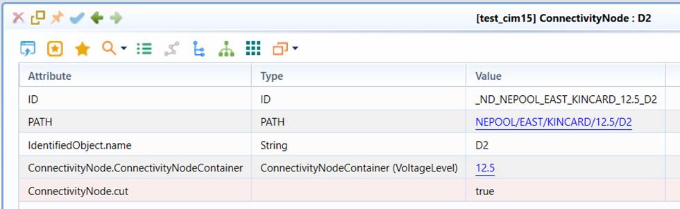
There are two purposes for marking POIs:
- Creating custom reports that display boundary/cut points.
- Supporting custom processes created in Python or C++ for integration/customization, for example adding parameters for equivalent loads/generators. This is the primary use. With POI marking, the relevant objects of interest can be quickly identified.
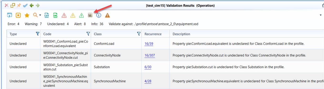
While creating custom reports is the formal way for displaying POIs, a quick way is to run model validation for the extracted sub-model. All of the marked POI objects will be reported as Undeclared objects, as illustrated below.
Summary of Configurations
The LV Network Reduction process is completely controlled by a set of configuration settings defined in a CSV file, i.e. \config\custom\lv_reduction\LVReductionSettings.csv. The CSV file is used because this is the format familiar to modeling engineers, even though it is not proper for defining structured settings. All of the configuration settings are defined as key/value pairs. As needed, conventions are used to declare some of the structured configuration settings. The following table summarizes all of the configuration settings.
| Key | Value (Example) | Description |
|---|---|---|
| LV_REDUCTION_CRITERIA | [ConnectivityNode.ConnectivityNodeContainer->VoltageLevel.BaseVoltage->BaseVoltage.nominalVoltage] < 137.999 |
The primary reduction LV network reduction rule in an MQL logical expression, used to identify ConnectivityNodes that are in LV sub-networks. Note: not all of the LV sub-networks that pass the primary rule will be removed. To be qualified for reduction, none of the supplementary rules shall be triggered. This rule is required. |
| LV_RETENTION_CRITERIA | [{Terminal.ConnectivityNode#[Terminal.ConductingEquipment->%ShortClassName] == SynchronousMachine}->%ObjectCount] > 0 |
Supplementary retention rule: similar to primary reduction rule, this supplementary rule is an MQL logical expression, but used to identify ConnectivityNodes in a LV sub-network that must be retained. For example, any LV sub-networks that contain a SynchronousMachine shall be retained. This rule is optional. |
| MIN_NODE_NUMB | 3 | Supplementary retention rule: if the number of ConnectivityNodes in a sub-network is less than MIN_NODE_NUMB, this LV sub-network shall be retained. This is to avoid reducing some very small LV sub-networks. This rule is optional. |
| MAX_TOTAL_GENERATION_CAPACITY | 20 | Supplementary retention rule: if the total installed generation capacity (sum of GeneratingUnit.maxOperatingP) is greater than MAX_TOTAL_GENERATION_CAPACITY, this LV sub-network shall be retained. This rule is used to retain major generation LV networks and eliminate LV sub-networks that contain small co-generation. Note: supplementary rules mustn’t be conflicting. For example, if rule MAX_TOTAL_GENERATION_CAPACITY is specified, rule LV_RETENTION_CRITERIA shouldn’t be declared to retain any LV sub-networks that contain a SynchronousMachine. This rule is optional. |
| RETAIN_TRANSFORMER | TRUE | If TRUE, transformers that connect LV with HV shall be retained. This is because these transformers normally carry useful ICCP measurements, which are critical for equivalence. |
| ADD_EQ_LOAD | TRUE | If TRUE, a specified type of load, i.e. EquivalentInjection, EnergyConsumer or its derived class, will be added for each cut point. |
| LOAD_TEMPLATE | ConformLoad/EnergyConsumer.pfixed=0; EnergyConsumer.qfixed=0 | Defining the class and properties of equivalent load in the form of ClassName/PropertyName1=PropertyValue1; PropertyName2=PropertyValue2… applicable only when ADD_EQ_LOAD is TRUE. |
| LOAD_NAME | EQLD | Default name of the equivalent loads, applicable only when ADD_EQ_LOAD is TRUE. |
| ADD_EQ_UNIT_MODE | 2 | Mode used to determin whether a generating unit (SynchronousMachine and GeneratingUnit) shall be added at a cut point. 0: not adding; 1 always adding; 2: adding only if the reduced LV sub-network has generation; 3: adding only if the reduced is a loop LV sub-network; 4: adding if the reduced is a loop LV sub-network or with generation. |
| UNIT_TEMPLATE | SynchronousMachine/RotatingMachine.ratedS =0; SynchronousMachine.minQ=0; SynchronousMachine.maxQ=0; SynchronousMachine.type= SynchronousMachineType.generator; SynchronousMachine.operatingMode =SynchronousMachineOperatingMode.generator | Defining the class and properties of equivalent synchronous machine in the form of ClassName/PropertyName1=PropertyValue1; PropertyName2=PropertyValue2… applicable only when ADD_EQ_UNIT is TRUE. |
| GEN_TEMPLATE | GeneratingUnit/GeneratingUnit.minOperatingP=0; GeneratingUnit.maxOperatingP=0 | Defining the class and properties of equivalent generating unit in the form of ClassName/PropertyName1=PropertyValue1; PropertyName2=PropertyValue2… applicable only when ADD_EQ_UNIT is TRUE. |
| UNIT_NAME | EQUN | Default name of the equivalent generating unit, applicable only when ADD_EQ_UNIT is TRUE. |
| USE_PATH_AS_ID | TRUE | If TRUE, object PATH will be used to generate rdf:IDs for equivalent objects. rdf:IDs generated from PATH are relatively persistent. Applicable only when ADD_EQ_LOAD or ADD_EQ_UNIT is TRUE. |
| PREFIX_STATION_NAME | TRUE | If TRUE, Substation name will be used as prefix of the names of the equivalent objects. Applicable only when ADD_EQ_LOAD or ADD_EQ_UNIT is TRUE. |
| APPENDIX_NUMBER | FALSE | If TRUE, number will be used as appendix of the names of the equivalent objects. Applicable only when ADD_EQ_LOAD or ADD_EQ_UNIT is TRUE. |
| MARK_POINT_OF_INTEREST | TRUE | If TRUE, points of interests (POIs), such as boundary objects, cut objects, and equivalent objects, will be marked as CIM extensions. With POI marking, the relevant objects of interest can be quickly identified, thus facilitating custom processes. |