Editing a Modeling Entity
One of the key features of the graphical model editor is support model editing in the graphical modeling environment. The main advantage of this feature over the classic object editing includes:
- It is more interactive. Users edit the model directly from the diagram and the background diagram provides good context information.
- The related CIM objects corresponding to a single modeling entity are grouped and presented as a whole, facilitating the data entry.
- Data and graphics are seamlessly integrated: what you see is what you get.
Editing a Network Component
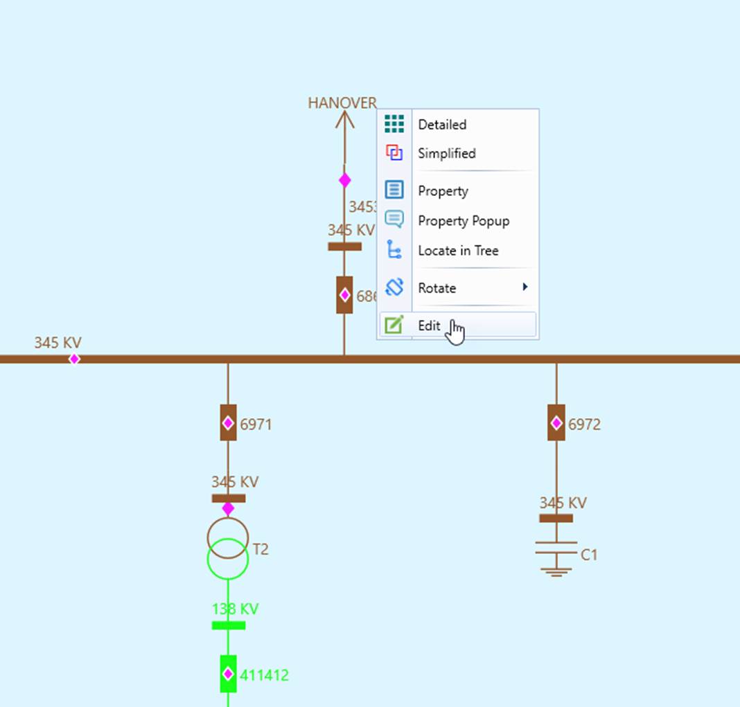
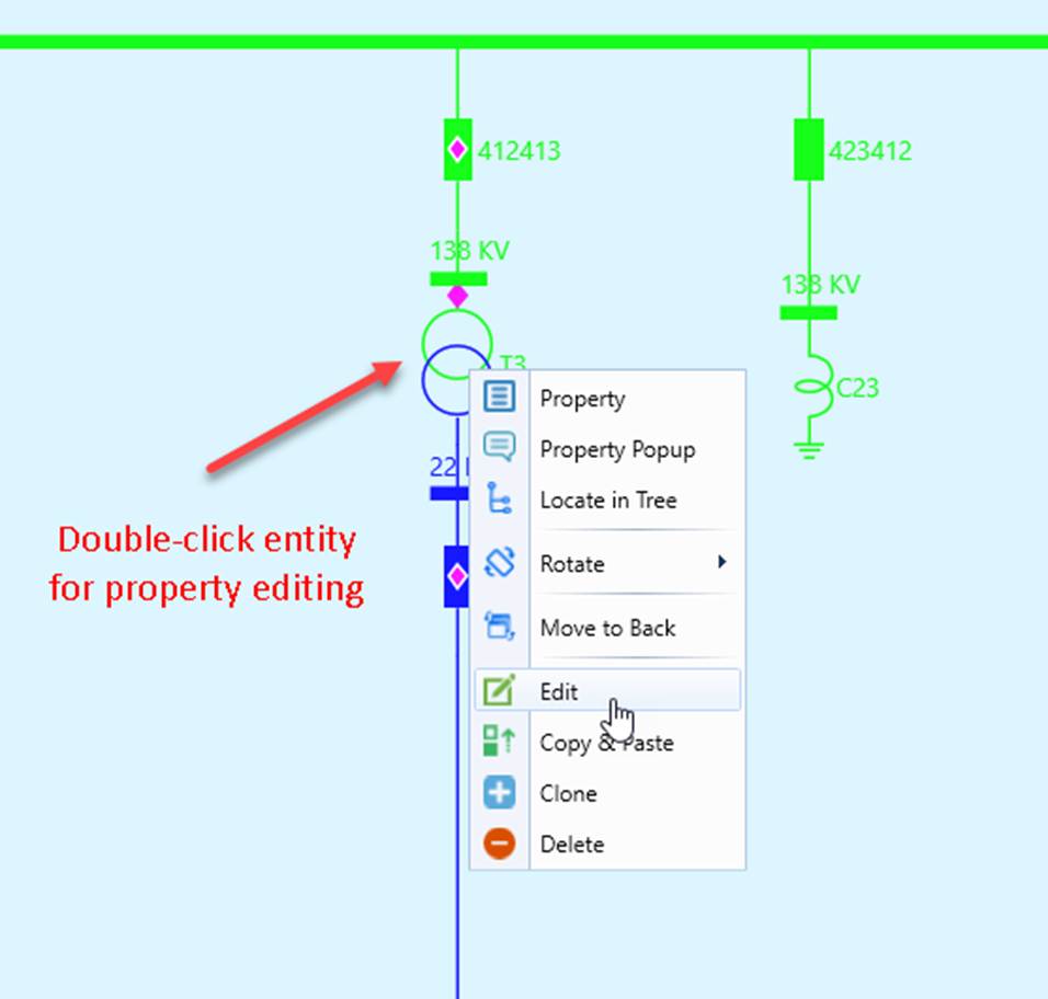
- In a graphical modeling environment, any network components, existing or newly added, are editable trough a popup edit box, which can be invoked by double-clicking the graphical symbol/label or via the context menu associated with the selected graphical symbol/label, as illustrated
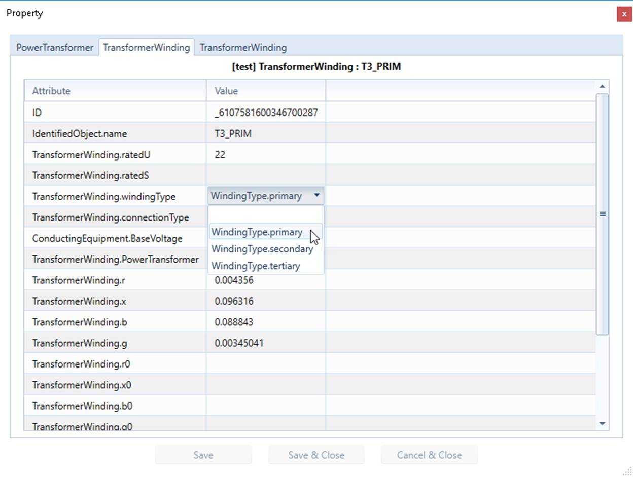
- Once invoked, a multi-tab property popup will be displayed. Each tab corresponds to a CIM object that composes the modeling entity. In the following example, the popup edit box consists of 3 CIM objects, 1 PowerTransformer and 2 TransformerWindings. The 3 CIM objects correspond to a single 2-winding transformer modeling entity. It is important to node the network connectivity information (such as Terminal) and the equipment/node containership (such as association Equipment.EquipmentContainer) as well as the composition (i.e. parent-child association) between the related CIM objects (such as TransformerWinding.PowerTransformer) are read-only in the popup form. Such information is set through graphical modeling activities, not editable through edit box. Users can edit such information either graphically or through object editor. The property popup is for entering the non-topological and non-hierarchical information.
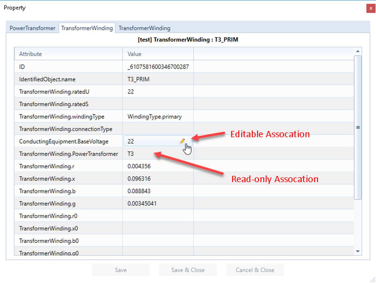
- Editing properties in a popup edit box is just like editing in an object Form Display. The modified properties will be highlighted in red, and users can also use the association wizard to select the referenced object, etc.
- Finally save or cancel the property changes.
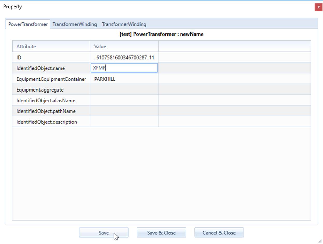
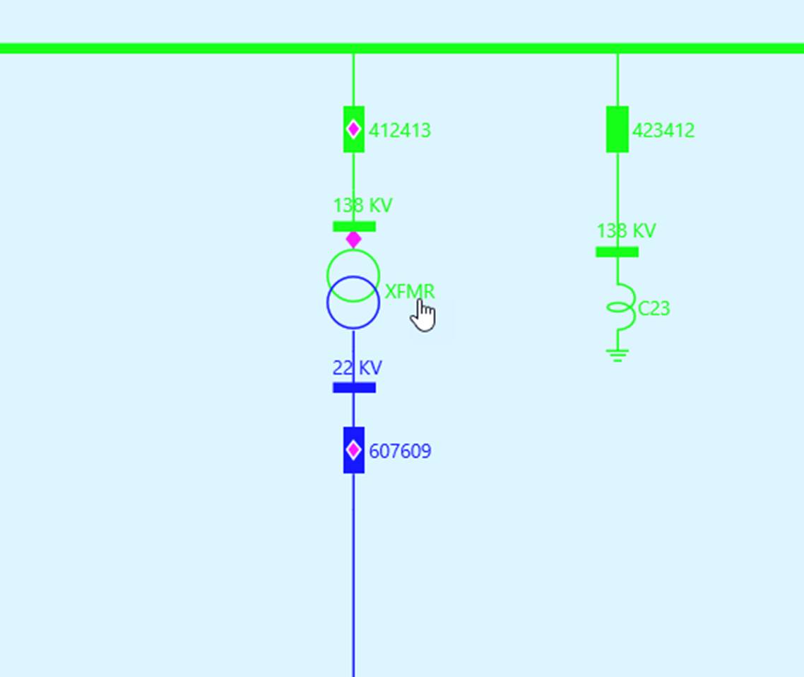
- After the changed property is saved, the diagram and the navigation tree will be automatically updated to reflect the property changes. In the above example, the transformer name is changed from T3 to XFMR. The label of the edited model entity and the corresponding object label in the navigation tree will be automatically updated, as shown below.
Editing a Substation
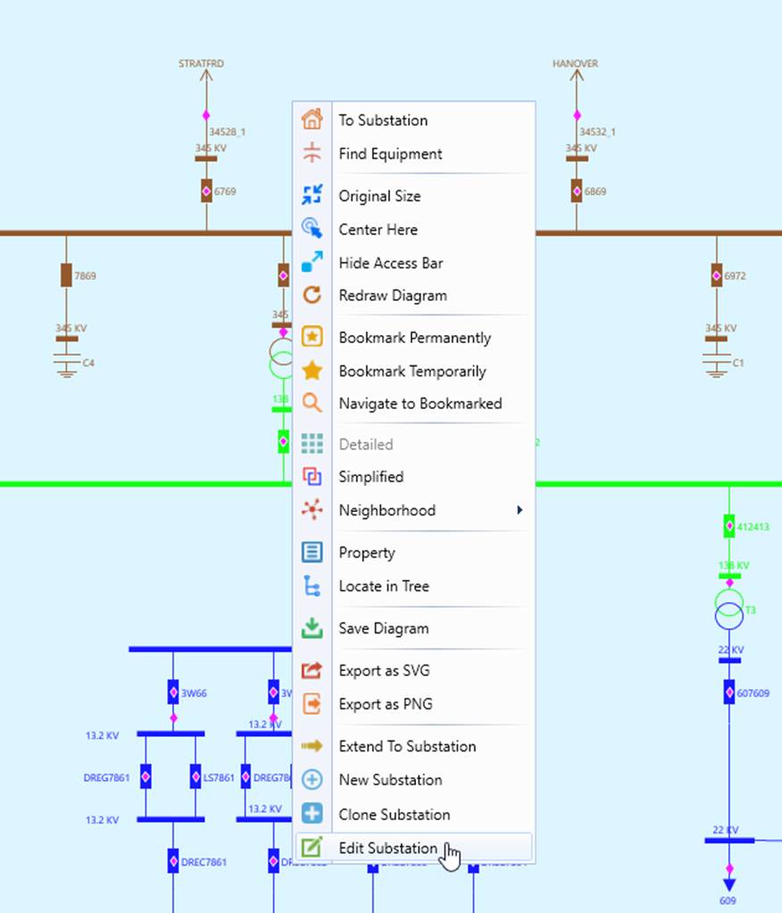
Substation property edit is just like equipment editing. Its popup can be invoked from either context menu or graphical labels as illustrated below.