Rich Data Visualization
Traditionally, the analytical results, such as those obtained from state estimation and power flow study, were displayed as numerical data in tabular forms. Experience has shown that human can recognize and analyze visual information much more quickly than they can do with numerical information. The rich data visualization features are designed to present data, raw or analytical, as easy-to-understand visual elements to promote interpretation and recognition of patterns.
Hands-On
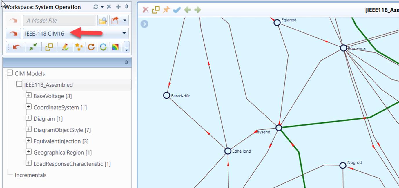
- Load sample model IEEE-118 CIM16 from data source dropdown. The geo diagram shall be displayed.
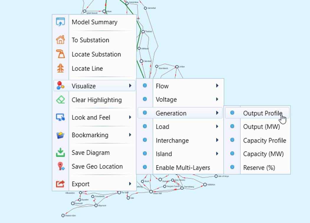
- Right-mouse-click a blank spot to invoke the context menu. Select Visualize→Generation→Output Profile.
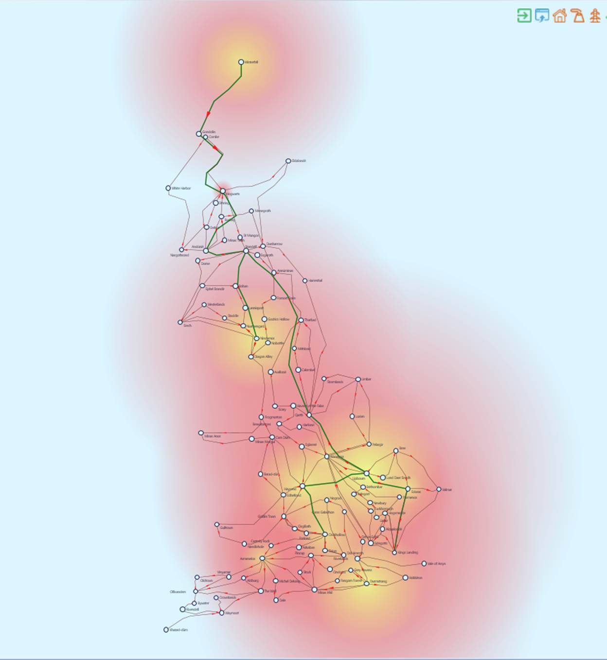
- Heat-map will be generated to display locations of the generation and magnitude.
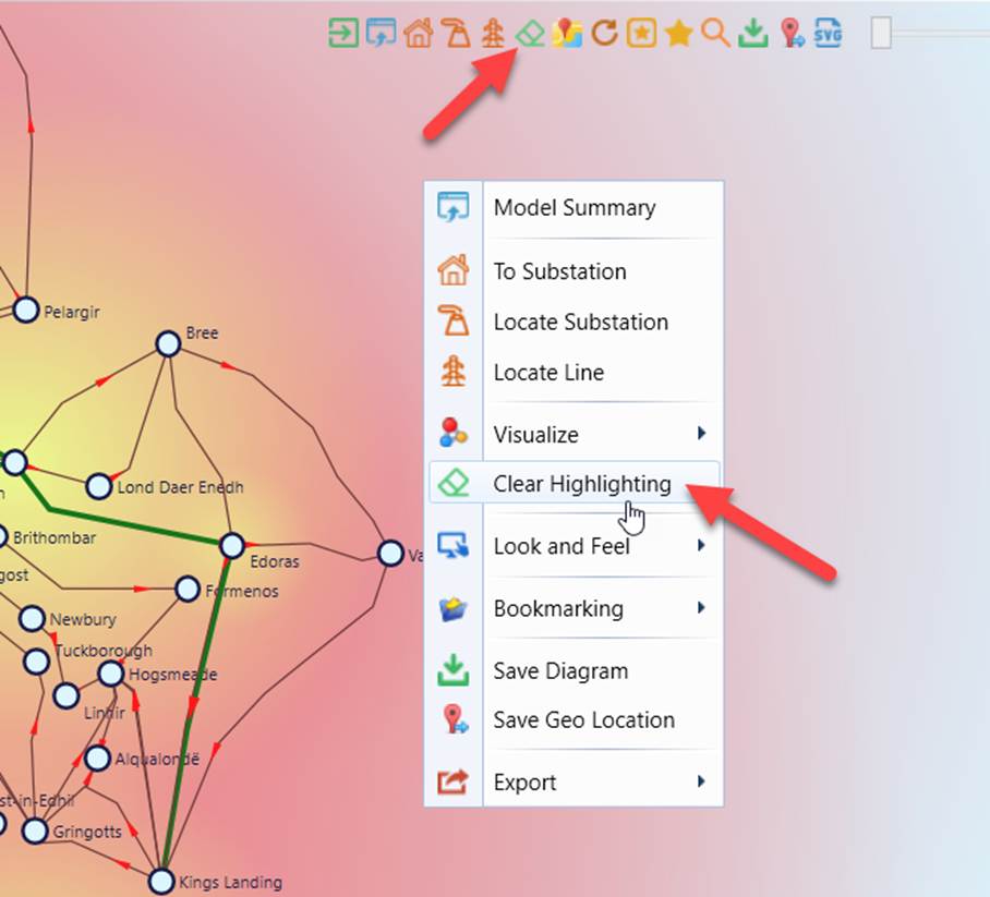
- Clear the visualization overlay.
Summary of Supported Data Visualizations
Data visualization is implemented as overlay. Two kinds of overlays are supported:
- Visualization Overlay: displaying location, magnitude, and patterns using heat map, color-based profiling techniques, etc.
- Data Overlay: displaying analytical results using text-visualization techniques, speed meter, etc.
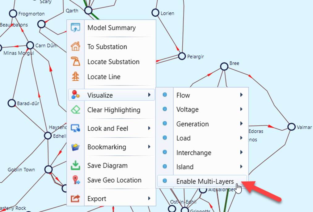
By default, only one overlay (called layer) is displayed. Users can enable multiple layers as illustrated below.
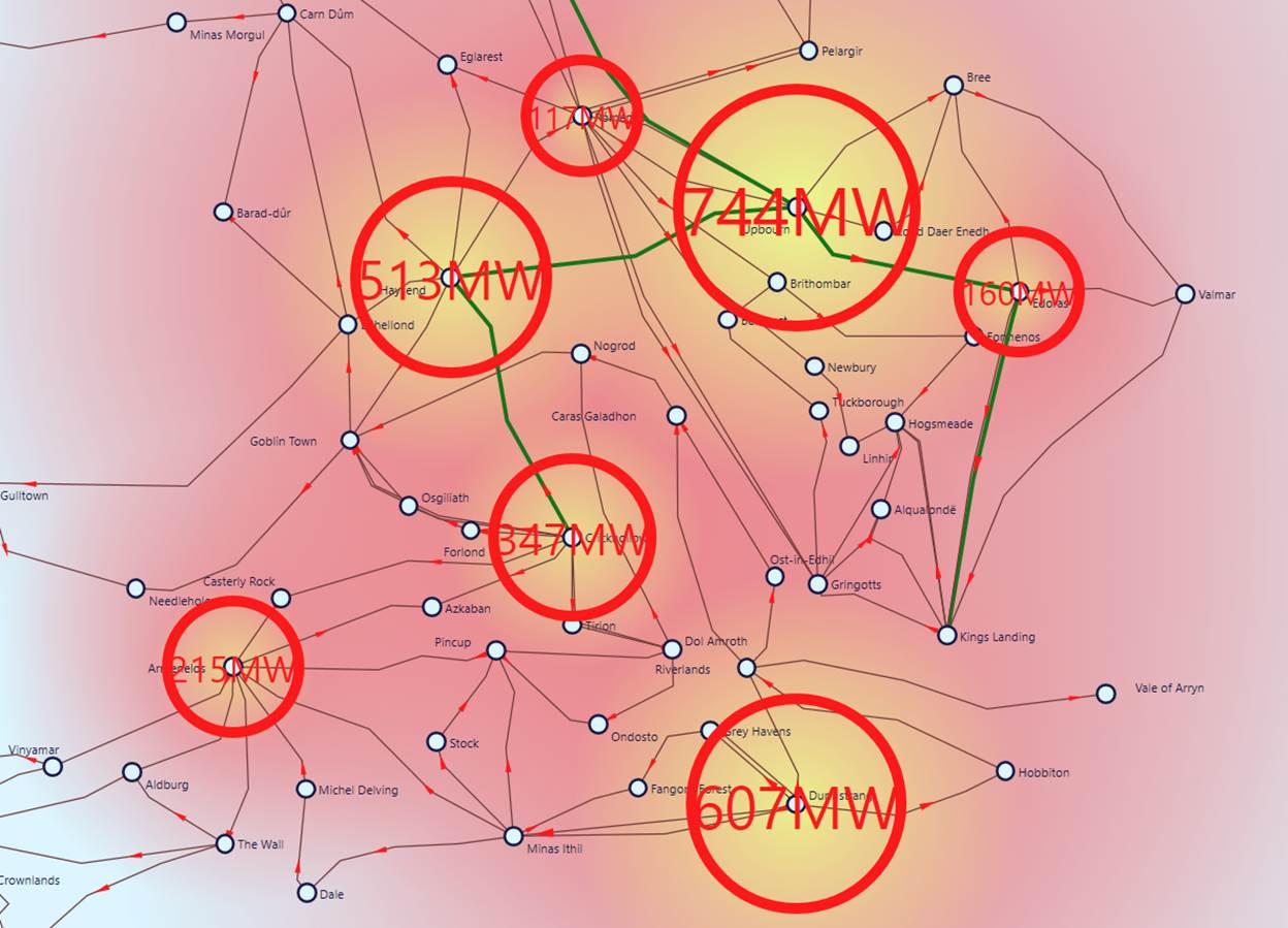
Once multi-layers are enabled, both visualization layer and data layer can be displayed together, as illustrated below.
The Tool supports various types of data visualizations, applicable to different types of diagrams. Most of them are for power flow visualization, thus requiring State Variables (SV) model parts to be available. Additionally, the Equipment (EQ) model part must contain some operational constraints, such as operational limits, generation capacity, etc. Data visualization is primarily for an assembled model.
The following table summarizes supported data visualization types, including types of diagrams applicable, overlay type, and required model parts.
Menu Item
Sub-Menu Item
Diagram
Overlay Type
Model Parts
Description
Flow
Limit Profile
Geographical Neighborhood
Visualization
EQ (with CurrentLimit or ApparentPowerLimit) + SV
Color branches with blended three colors to check power flow against limit (green – below limit, yellow – close to limit, and red – above limit ). Mouse over the colored area will display numeric data using speed meter.
Overlimit Only
Geographical Neighborhood
Visualization
EQ (with CurrentLimit or ApparentPowerLimit) + SV
Highlight over-limit branches with red color. Mouse over the colored area will display numeric data using speed meter.
Loss Profile (MW)
Geographical Neighborhood
Visualization
EQ (with CurrentLimit or ApparentPowerLimit) + SV
Color branches with blended three colors to visualize line loss in MW (green – low loss, yellow – average loss, and red – high loss). Mouse over the colored area will display numeric data using speed meter.
Loss Profile (%)
Geographical Neighborhood
Visualization
EQ (with CurrentLimit or ApparentPowerLimit) + SV
Color branches with blended three colors to visualize line loss in percentage (green – low loss, yellow – average loss, and red – high loss). Mouse over the colored area will display numeric data using speed meter.
Angle Profile
Geographical Neighborhood
Visualization
EQ (with CurrentLimit or ApparentPowerLimit) + SV
Color branches with blended three colors to visualize phase angle loss (green – low phase angle, yellow – average phase angle, and red – large phase angle). Mouse over the colored area will display numeric data using speed meter.
Angle Degree
Geographical Neighborhood
Data
EQ (with CurrentLimit or ApparentPowerLimit) + SV
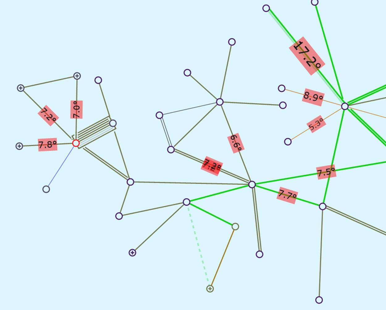
Display numeric line phase angle value in degree with red highlighted background. The size of the text block is proportional to the numeric value.
Large Angle Only
Geographical Neighborhood
Visualization
EQ (with CurrentLimit or ApparentPowerLimit) + SV
Highlight branches with large phase angle. Lines with large phase angles will be highlighted with red color. Mouse over the highlighted branch will display the angle value.
Voltage
High Limit Only
Substation Geographical Neighborhood
Visualization
EQ + SV
Highlight substations/nodes above the high voltage limit (1.1 PU by default) with the heat map.
High Limit Profile
Substation Geographical Neighborhood
Visualization
EQ + SV
Color substations/nodes with blended three colors to check voltage magnitude against high voltage limit (1.1 PU by default) (green – below voltage limit, yellow – close to voltage limit, and red – above voltage limit ). Mouse over the colored area will display numeric data using speed meter.
Low Limit Only
Substation Geographical Neighborhood
Visualization
EQ + SV
Highlight substations/nodes below the low voltage limit (0.9 PU by default) with the heat map.
Low Limit Profile
Substation Geographical Neighborhood
Visualization
EQ + SV
Color substations/nodes with blended three colors to check voltage magnitude against low voltage limit (green – above low voltage, yellow – close to low voltage limit, and blue – below voltage limit ). Mouse over the colored area will display numeric data using speed meter.
All Limit Violations
Substation Geographical Neighborhood
Visualization
EQ + SV
Highlight substations/nodes with voltage below the low voltage limit or above the high voltage limit in the same diagram. (blue – below voltage limit, red – above voltage limit ).
Generation
Output Profile
Geographical Neighborhood
Visualization
EQ + SV
Display location and magnitude of power plant generation output using heat map. The “hotness” in color and the size of the influence is proportional to the generation output.
Output (MW)
Geographical Neighborhood
Data
EQ + SV
Display power plant generation output in MW using text visualization. Size of the circle is proportional to the numeric value. Mouse over will display value in clear text.
Capacity Profile
Geographical Neighborhood
Visualization
EQ
Display location and magnitude of power plant generation capacity using heat map. The “hotness” in color and the size of the influence is proportional to the generation capacity.
Capacity (MW)
Geographical Neighborhood
Data
EQ
Display power plant generation capacity in MW using text visualization. Size of the circle is proportional to the numeric value. Mouse over will display value in clear text.
Reserve
Substation Geographical Neighborhood
Data
EQ + SV
Display power plant generation reserve (i.e. energy generation output data with respect to capacity limit) using speed meter.
Load
Profile
Geographical Neighborhood
Visualization
EQ + SV
Display location and magnitude of energy consumption using heat map. Instead of red-hot color, a dark-blue-cold color is used to simulate power drain. The larger and darker the influence, the bigger the consumption.
Demand
Geographical Neighborhood
Data
EQ + SV
Display substation energy consumption in MW using text visualization. Size of the circle is proportional to the numeric value. Mouse over will display value in clear text.
Interchange
By Region
Geographical Neighborhood
Visualization
EQ + SV
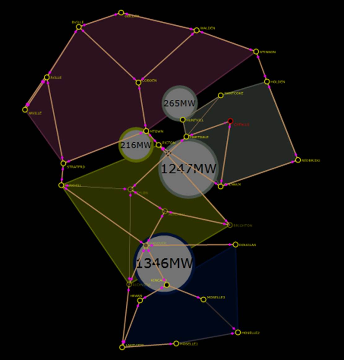
Group Substations by GeographicalRegions using a colored polygon overlay and display interchange in MW among them using animated text visualization.
By Sub-Region
Geographical Neighborhood
Visualization
EQ + SV
Group Substations by SubGeographicalRegions using a colored polygon overlay and display interchange in MW among them using animated text visualization.
Region and Tie
By Region
Geographical Neighborhood
Visualization
EQ
Group Substations by GeographicalRegions using a colored polygon overlay and highlight tie-lines among GeographicalRegions.
By Sub-Region
Geographical Neighborhood
Visualization
EQ
Group Substations by SubGeographicalRegions using a colored polygon overlay and highlight tie-lines among SubGeographicalRegions.
Generation Reserve
Substation
Data
EQ + SV
Display generator generation reserve (i.e. energy generation output data with respect to capacity limit) using speed meter.
Visualization Techniques
This section briefly describes how some of the state-of-the-art visualization techniques are applied to help users cognitively read the system operating conditions.
Energy Generation and Consumption
A heat map is a raster map showing the density or magnitude of point related information. It is a two-dimensional representation of data in which values are represented by colors and areas of influence. A heat map can provide an immediate visual summary of information. It also helps users to extract the patterns from large amount of data. There are many ways to display heat maps, but they all share one thing in common -- they use colors and areas of influence to communicate relationships between data values that would be, otherwise, much harder to understand.
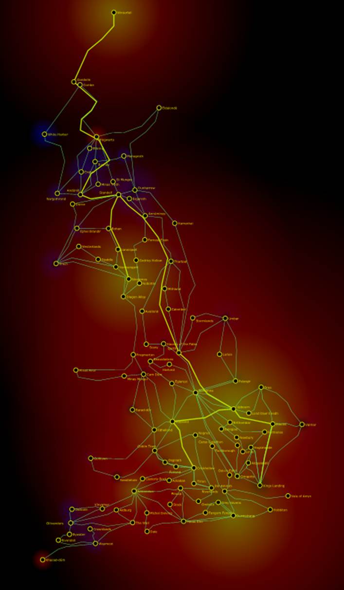
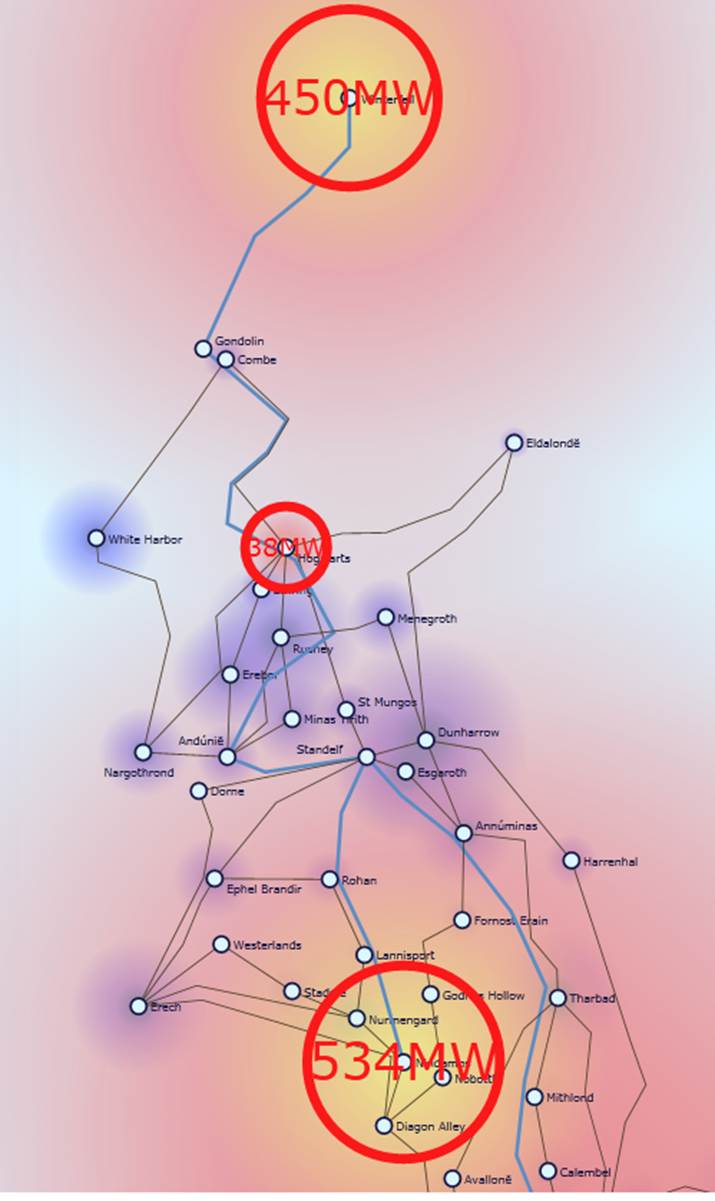
The heat map in the following figure presents a visual summary of energy generation and consumption in a small test grid. The red color represents energy generation and the blue color represents the energy consumption. The energy generation/consumption heat map not only describes where the electric energy is generated and consumed, but also indicates the magnitude of the energy generation and consumption. Power plants that generate large amount of energy result in “solar core” within large “hot” areas, while the main demand centers produce the black core in blue consumption areas. The energy generation/consumption heat map enables operators to instantly understand the energy distribution in a power grid.
Operational Constraint Violation
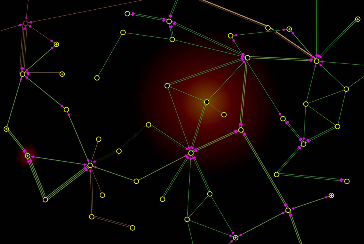
Similarly, heat map based visualization technique can also be applied to monitor other key operational quantities. The following diagram highlights two Substations where voltage limit violations occur in a Neighborhood Diagram. Additionally, it clearly indicates how severe the over-limiting situations are for each substation.
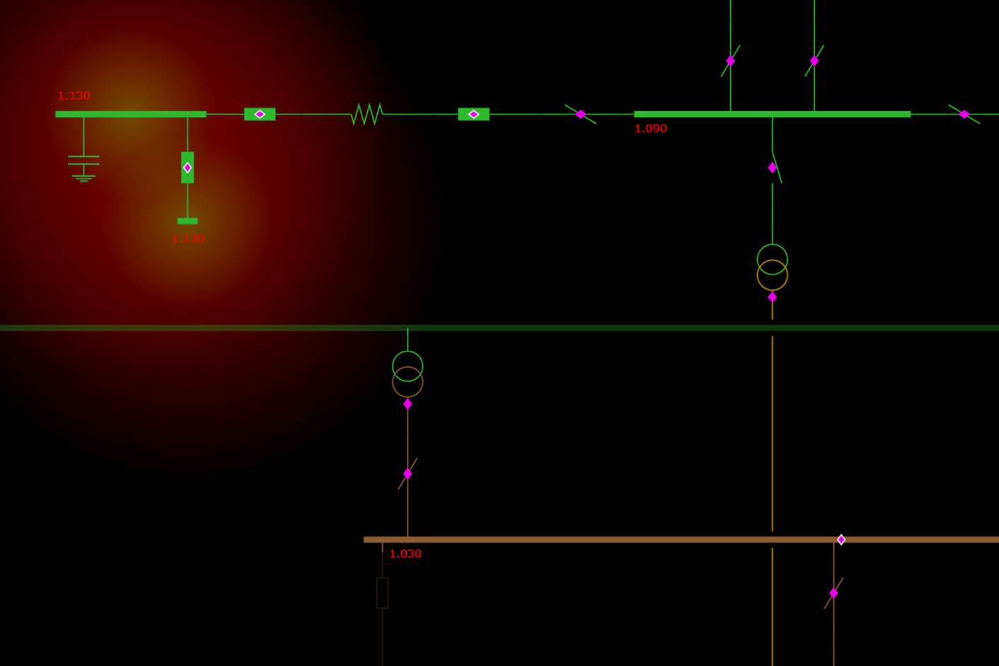
By navigating to the corresponding Substation Diagram, users can quickly identify what causes violation of high-voltage limit from the heat map inside the Substation: over-compensation by a ShuntCompensator. The over-limiting condition then can be easily mitigated by opening the Breaker connecting to the ShuntCompensator.
Voltage and Flow Profiling
For secure operation of power grids, system operators in a control center must closely monitor various operations constraints to ensure that the grid is at a “healthy” state. The major blackouts are often triggered by violations of the security constraints. Traditionally, the real-time security constraints are displayed using numerical information in tabular displays, which are very difficult to interpret.
A fuzzy logic based visualization technique was applied to provide users an overall picture of the system health from various perspectives: voltage, power flow, frequency, etc. Basically colors are used to communicate the ‘meaning’. This is based on the fact that humans are much more cognitively sensitive to color than numeric. More specifically, three colors are used to indicate the health condition of a measured/analyzed quantitative: green (healthy), yellow (warning), and red (alarming), each representing a defined quantitative range using a fuzzy model. Then we mix each color ingredient using fuzzy logic operations based on the actual measured/analyzed value. With the blended color, users can profile the related portion of the diagram, providing user an overall picture of the grid health.
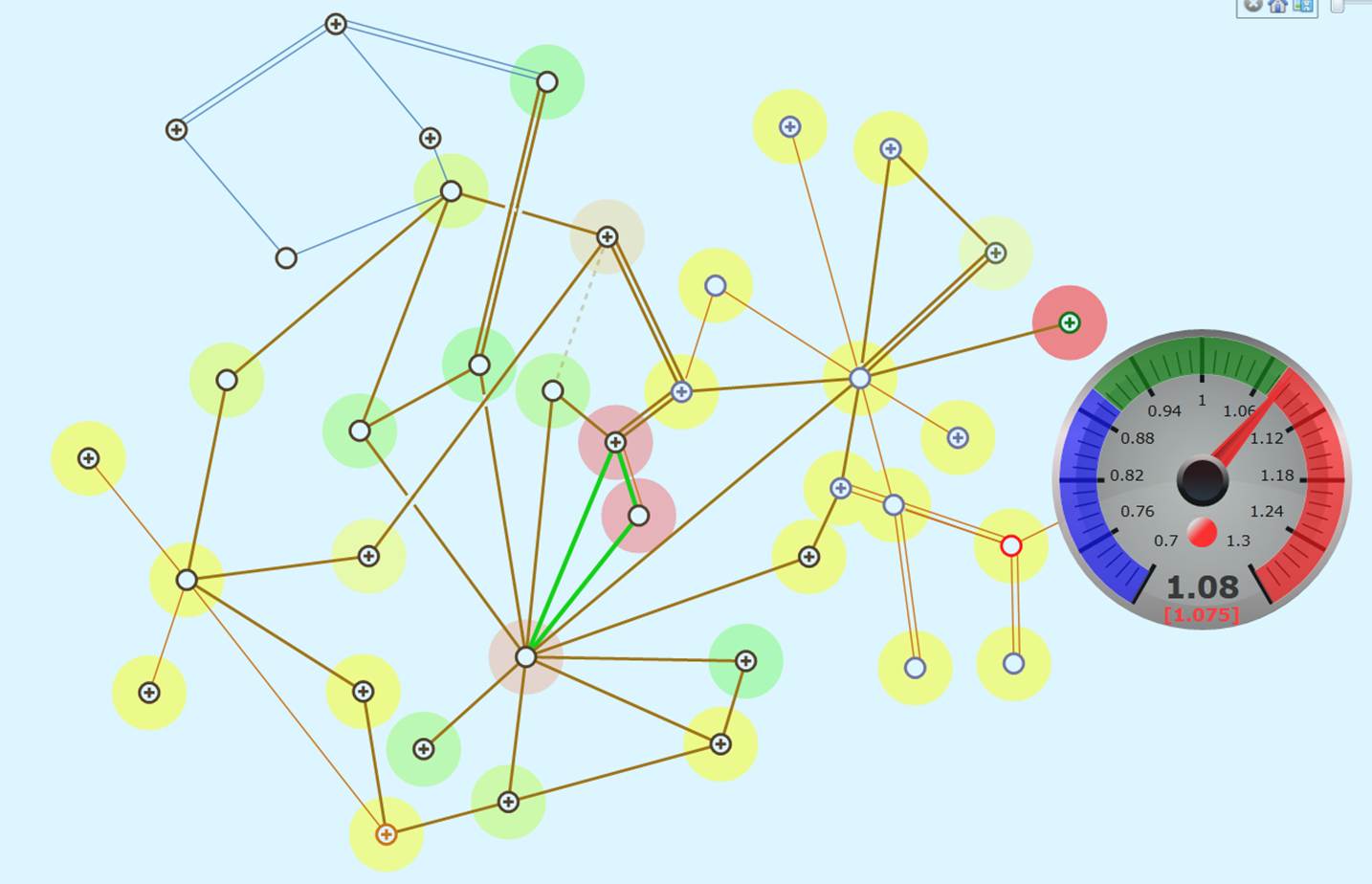
The voltage profile shown in the following sample illustrates such a use case. System voltage profile is a key quantitative indicator monitored by grid operators. Excessively high voltage could cause equipment to malfunction, while the voltage below the low limit could result in the system to collapse. The fuzzy color based voltage profile, as illustrated below, can help operators immediately identify the potential voltage problems and timely enable the preventive or remedial actions.
The power flow congestion profile, shown in the following figure, is another example demonstrating how fuzzy coloring visualization can be applied to help the grid operators monitor the system health from the energy transaction perspective. A transmission line colored as “alarming red” means that the flowing current is close to its capacity or rated current limit. The redness indicates how serious the represented condition is. It prompts the grid operators to change the operation configurations to relive the congestion in the identified transmission lines.
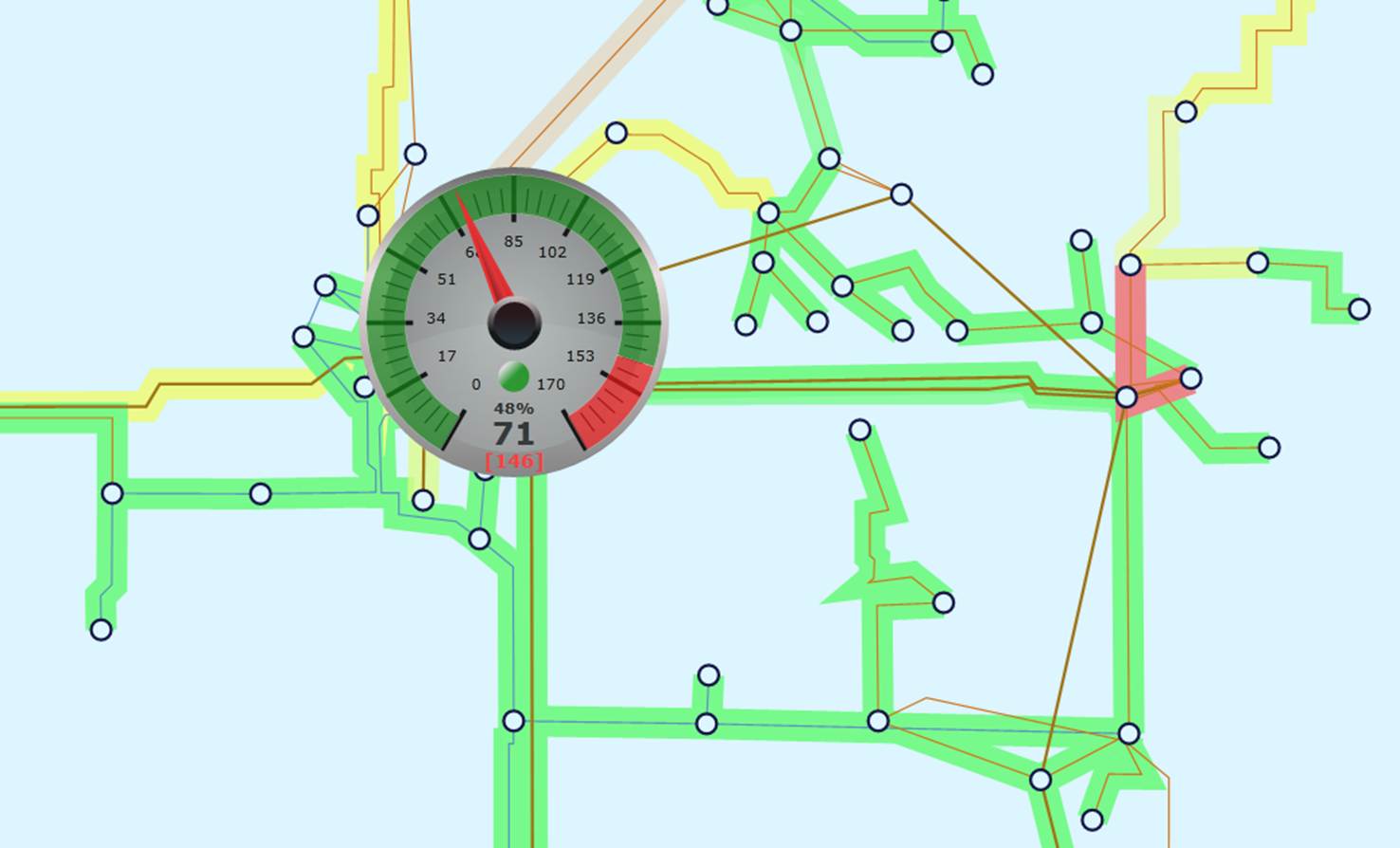
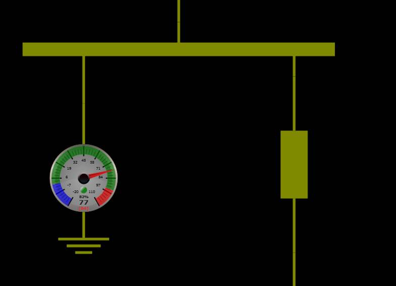
Another technique used is on-demand graphical presentation of quantitative information. Experiments conducted have concluded that presenting too much numerical information in a visual display could result in “information overload” and distraction. The idea is to use the conceptual visualization techniques, such as fuzzy color profiling, to provide users a general feeling, but enable users to call a diagram display on demand to view more accurate information. For example, by moving mouse cursor over a colored graphical symbol that represents as a selected transmission line, operators can find out how closely the voltage/power flow is approaching to its rated limit through a numerically labeled speed meter, as illustrated in the above diagrams.
Generation Reserve
Simply creating visualizations to display data provides limited assistance, especially in a power grid control center where system operators must monitor and analyze large amounts of information and respond to problems before disruptions can arise. To help users understand the operational data, the Tool leverages various state-of-the-art rich data visualization techniques designed to present raw data as easy-to-understand visual elements.
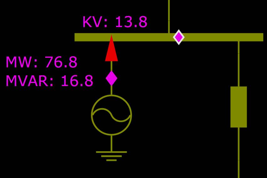
The following diagrams illustrate how rich data visualization can help operators perceptually monitor the MW output from a generating unit. The left diagram simply presents the real-time measurements of a generating unit, while the right diagram presents the same information using a numerically labeled speed meter, which displays not only the current MW output of a generating unit, but also its generation reserve. The maximum and minimum operating limits are marked as red and blue respectively.
Phase Angle
While graphical presentations, such as colors, shapes, and animations, help grid operators perceptually monitor grid operating conditions, more accurate numeric data are needed to support decision making in many cases. On the other hand, the numeric data presented in this traditional format are hard to read, track, and identify correlation and relationships between them.
The Tool presents numeric data in a way that fosters understanding and reduces cognitive demands. The applied text visualization is an effective way to facilitate decoding of the quantitative information. It uses visual representation to present texts, thus adding another dimension for presentation of numeric data. For example, the phase angle diagram, as illustrated below, presents the numeric data in a shape with its size reflecting the value of the represented numeric data. It shifts users focus to those large phase angle differences that requiresspecial attention, since breakers may not operate normally if the phase angle is too large.
Regional Energy Interchange
Energy transaction among regions is one of the key performance indexes monitored by the system operators. The Tool is capable auto-generates the regional schematic and geographical diagrams and then uses the animation to illustrate the inter-exchanges among regions. The following diagram illustrates such an example. The circles that represent the exchanged MW move from one region to another, providing operators an intuitive summary of current inter-exchange among four operating areas.
Configuration and Customization
Rich data visualization is governed by configuration file \config\style\RichData.xml.
Rich data visualization uses various graphical visualization techniques including: heat map, fuzzy color and graphical text presentations, to help grid operators to understand the system conditions and alarming events. The system characteristics regarding normal, warning, alarming levels, for example, are different from one utility to another. There are no one-size-fit-all settings. Users are given flexibility to customize visualization settings to fit their own needs. This is accomplished by changing Presentation Style under RichDataVisStyle >> RichDataVisualization. In RichDataVisualization section, there are a few visualization type elements: HeatMap, TextDataLine, MeterGauge, and ColorMap. They are applied to each visualization feature with applyTo attribute. In most cases, users should only change the attributes of the child setting elements, such as NumberOfPointsShown -> value, Color -> hex, or Color -> cutoffMaxInclusive. Let’s look at each visualization type in details.
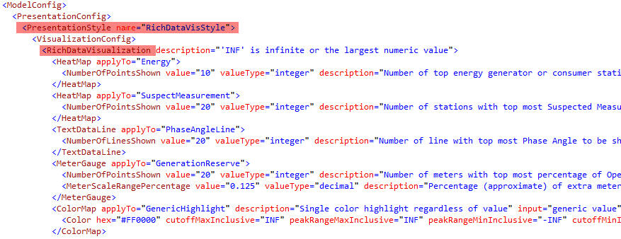
- HeatMap – HeatMap is used in a few visualization features. In Energy (both generation and consumption) and Measurement: Suspected Measurement, there are often too many HeatMap points to be clearly displayed in the diagram. Users could set the maximum number of points (NumberOfPointsShown) to be displayed at the same time. The points with the highest intensity (generation output or bad measurement count) will be displayed first. The default value is 10 and 20 respectively.
- Note: the respective Quantitative Data Views for Energy and Bad Measurement are also governed by these settings. The number of circles with numeric value is the same as that of the HeatMap points.

- TextDataLine – TextDataLine is used in Quantitative Data View of Profile: Line Phase Angle, the phase angle value displayed in text along the line. Users could set the maximum number of lines (NumberOfLinesShown) whose phase angels will be displayed at the same time. The largest phase angles will be displayed first. The default value is 20.

- MeterGauge – MeterGauge (Speedo Meter display) is used in a few visualization features. For displaying Quantitative Data View of Energy: Generation Reserve, there can be too many meters to be clearly displayed in the diagram at the same time. Users could set the maximum number of meters (NumberOfPointsShown) to be displayed at the same time. The highest generation output will be displayed first. The default value is 20. Optionally, users could also set the ratio of extra scale range beyond the limit (MeterScaleRangePercentage). This extra range is used to display over-limit value. If not defined, the default value is 0.125 or 12.5%.

- ColorMap – ColorMap is used in all color visualization features, including simple highlighting and fuzzy color presentation. It can be applied to either points or lines. Within ColorMap, one or more Color elements can be defined. A fuzzy color presentation will take the blended effects from all color components. Take a example of the LineLossMW color definition shown below: the alarming red color takes full effect above 10MW loss. From 10MW to 5MW, it gradually loses effect. The warning yellow color takes the opposite trend in the range. There is no red alarming effect after 5MW. Warning yellow takes full effect between 5MW and 3MW and loses effect after that. The normal green starts to take effect from 3MW and reaches maximum effect between 1MW and 0MW. All negative losses, excluding 0MW, are shown with out-of-range blue color.

- Color Element – Each Color element controls a color component. The Color element has 5 user defined attributes. (Use INF for the positive largest value and -INF for the negative largest value)
- hex – the standard color RGB definition is hex value.
- cutoffMaxInclusive or cutoffMaxExclusive – the upper limit of the input value range. If input value is larger than this value, this color will have no effect in the fuzzy color blend. Inclusive and Exclusive decides if this cutoff value is part of the range, which is important for color highlight.
- peakRangeMaxInclusive or peakRangeMaxExclusive – peak range is the range of input value, where the color has the maximum effect in the fuzzy color blend. peakRangeMax defines the upper bound of this range. Similarly Inclusive and Exclusive decides if this value is part of the range.
- peakRangeMinInclusive or peakRangeMinExclusive – defines the lower bound of the peak range, beyond that the color loses maximum effect. Similarly Inclusive and Exclusive decides if this value is part of the range.
- cutoffMinInclusive or cutoffMinExclusive – the lower limit of the input value range, beyond that the color will have no effect in the fuzzy color blend. Similarly Inclusive and Exclusive decides if this value is part of the range.
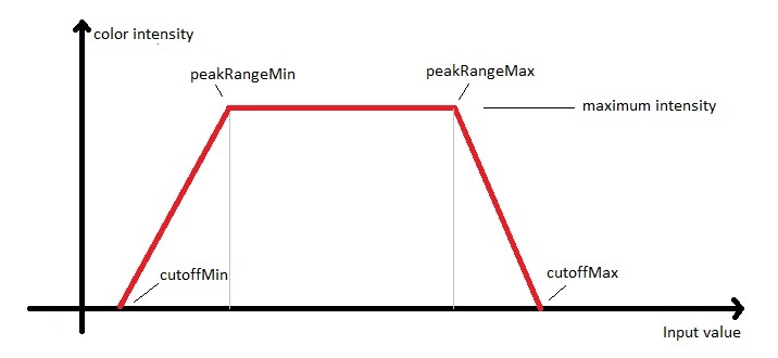
- Single Color Highlight – for highlighting either a point or a line, only one Color component is needed. Normally, a limit is defined by both cut-off and peak-range value. Any input value greater or smaller than the limit will be highlighted in color. In the following LineAngleLimit example: the line will be highlighted in red color if the angle value is larger than 15 degree.

- Supported Visualization Features:
- GenericHighlight – no upper or lower limit. Point or line will always be highlighted if applied. Used on transaction tie-lines.
- LowKVMargin – define fuzzy color profile for low voltage.
- HighKVMargin – define fuzzy color profile for high voltage.
- LinePowerLimit – highlight lines with over-limit power.
- LinePower – define fuzzy color profile for line power ratio over rating limit.
- LineLossMW – define fuzzy color profile for line loss in MW.
- LineLossPercentage – define fuzzy color profile for line loss in percentage ratio over rating limit.
- LineAngleLimit – highlight lines with over-limit phase angle.
- LineAngle – define fuzzy color profile for line phase angle.