Exporting External Network
Overview of External Network Modeling
For accurate security analysis, a significant portion of external network must be properly modeled and timely updated in operational systems, such as Energy Management Systems (EMS). Traditionally, this is a time-consuming and error-prone manual process. Even more challenging is to keep external models timely updated. Availability of region-wide EMS models makes it possible to build an automated external network modeling process. An automated external network modeling process must meet the following requirements:
- A repeatable solution that automates external network modeling process end-to-end.
- Human analysts are still tightly involved in the loop. But their roles should be minimized.
- The established automation must be capable of supporting two key processes:
- Initial Model Merging
- Recurring Model Update
External network modeling is normally a highly customized process driven by specific requirements. There is no one-size-fit-all solution. There are many options available. The goal is to apply the identified best practices to build a solution meeting your evolving and long-term modeling requirements. The following figure describes a typical process for external network modeling.
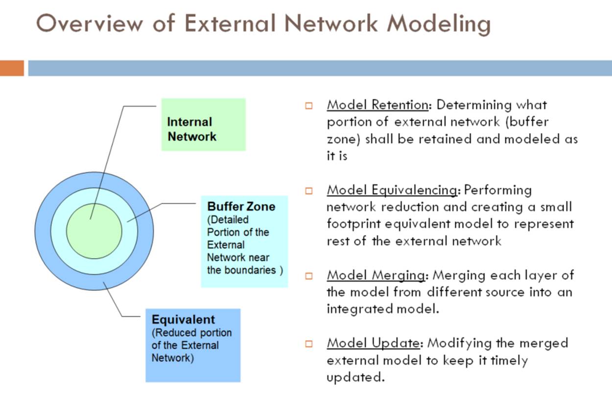
Overview of External Model Export
In order to support external network modeling, the Tool provides a function, enabling users to extract a portion of network models from a CIM based regional or neighboring network model. The extracted portion of network model is normally retained subset of network near the boundary (referred to as buffer zone). It can be integrated with the internal network model to create a new or updated EMS model. More specifically:
- The External Model Export function extracts a subset of network model (referred to as buffer zone) from a regional or neighboring CIM models based on user-specified definitions.
- The extracted buffer zone is a complete data set, including equipment, measurement, connectivity, curve, schedule…
- Model extraction is highly configurable. Users can define buffer zones by regions, boundary stations, neighborhood levels…
- Equivalent injections (load, generating units, or EquivalentInjections) can be optionally placed at the cut points.
- Flags can be optionally added as CIM extensions to mark points of interest, including cut points, stitching points, tie-lines, equivalent injections, etc.
- The External Model Export function works for any versions of CIM.
While the External Model Export function is not an out-of-the-box solution, it significantly reduces engineering effort needed to build a custom solution for external network modeling, in collaboration with existing data engineering support, such as model transformation, custom reporting, Python scripting, etc.
Hands-On
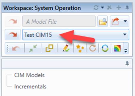
- Load “Test CIM15” sample model from the model source dropdown.
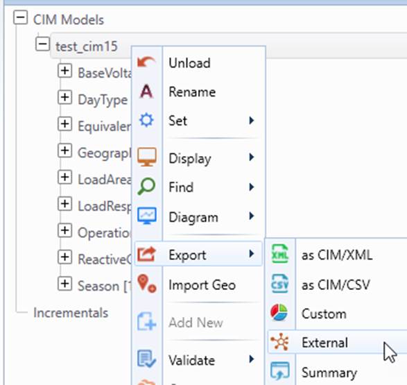
- Invoke External Model Export from the corresponding context menu (i.e. Export→External) associated with the loaded model.
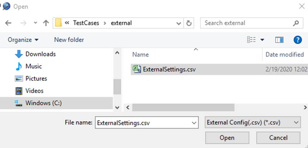
- Select the configuration CSV file \TestCases\externa\ExternalSettings.csv.
- A new model shall be created, containing only the specified external network sub-model.
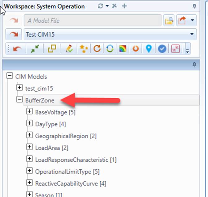
Buffer-Zone Definition
The External Model Export process is governed by a set of configuration settings defined in a CSV file. All of the configuration settings are defined as key/value pairs and summarized at the end of this article. Among these settings, the most important are definitions of buffer zone, which is an enclosed sub-network. Buffer zone definitions primarily include:
- BOUNDARY_DEFINITION: defining the boundary between internal and buffer zone. The boundary is defined by a set of (internal) boundary Substations and boundary branches. Note: boundary Substations and boundary branches must exactly match. For each boundary branch, the connected Substation located in the Internal must be defined as boundary Substation in the BOUNDARY_DEFINITION.
- CUT_DEFINITION: defining how the buffer zone shall be cut from rest of the external network. This is defined by a set of Substations that are connected to the buffer zone, but shall not be included in the buffer zone. These Substations are referred to as Cut Substations.
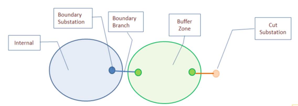
While Substations are the raw elements for defining buffer zone, regions (GeographicalRegion/HostControlArea) and sub-regions (SubGeographicalRegion/SubControalArea) can also be used to define buffer zone based on the following rules:
- When a region/sub-region is declared in BOUNDARY_DEFINITION, all of its internal boundary Substations and tie-lines are treated as boundary Substations and boundary branches.
- When a region/sub-region is declared in CUT_DEFINITION, all of its external boundary Substations are treated as cut Substations, except those located in the Internal.
Both BOUNDARY_DEFINITION and CUT_DEFINITION are declared as one or more triplets. Multiple triplets are separated by ‘|’. A triplet is declared in the following format:
Class_Name / Identifier_Type : Identifier_Values
Where:
- Class_Name: Name of the classes. For BOUNDARY_DEFINITION, valid class names are Substation, ACLineSegment, SeriesCompensator, GeographicalRegion, SubGeographicalRegion, HostControlArea, SubControalArea. For CUT_DEFINITION, valid class names are Substation, GeographicalRegion, SubGeographicalRegion, HostControlArea, SubControalArea.
- Identifier_Type: Type of the identifiers. Valid types are Name and ID. Note: Name is more informative, but it can only be used when names of the related objects are unique model-wise.
- Identifier_Values: Values of the identifiers. Multiple values are separated by ‘;’. If Identifier_Type is Name, Identifier_Values shall match IdentifiedObject.name or Naming.name (for CIM 10). If Identifier_Type is ID, Identifier_Values shall match rdf:IDs.
As an example, the following defines the buffer zone in the hands-on sample.

In the above example, all of the internal boundary Substations of GeographicalRegion ECAR are defined as boundary Substations and the corresponding tie-lines are defined as boundary branches. Substation COBDEN, BVILLE, and all of the external boundary Substations of SubGeographicalRegion NORT (except those in GeographicalRegion ECAR) are defined as cut Substations.
Optionally, Identifier_Values can be from a separate CSV file. In this case, the Identifier_Values must be the corresponding CSV file path with ‘csv’ as extension name of the file. For example, the following CUT definition specifies that the Identifier_Values are from a separate CSV file.

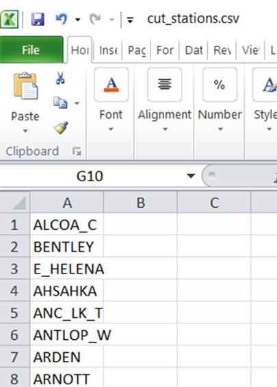
In summary, a buffer zone can be defined by Substations, regions, sub-regions, or a combination of them. The buffer zone defined must be an enclosed sub-network connected to the Internal at Boundary Substations and rest of the External at the Cut Substations.
At run-time, the External Model Export process searches for the buffer zone starting from the Boundary Substations/Branches. The process uses a width-first search algorithm to identify all of the contained network components and the related modeling entities. The search process is bounded by the defined Cut Substations. Additionally, the process can be controlled by a set of configuration settings, as described below:
- If CUT_DEFINITION is not defined, the search process will be unbounded. That normally means the whole external network is intended to be retained.
- Configuration setting MAX_DEPTH is used to restrict the search within a certain depth. This setting can also be used to extract a buffer zone based on the neighborhood distance, for example, a buffer zone containing all of the Substations that are within distance of 5 branches.
- Configuration setting MAX_NUMB_OF_STATIONS is used to detect whether the search goes beyond the intended buffer zone. The search will be aborted if the number of the retained Substations is greater than MAX_NUMB_OF_STATIONS. This configuration shall be set to a number that is greater than the estimated number of Substations in the buffer zone. In this case, once MAX_NUMB_OF_STATIONS is reached, this normally means CUT_DEFINITION is either incomplete or incorrect.
- Buffer zone doesn’t have to complete external. It could be partial external network. In this case BOUNDARY_DEFINITION/CUT_DEFINITION shall be elaborately defined to ensure only the designated portion of the external network shall be extracted.
Once the buffer zone is successfully identified, a separate model will be created. It contains only the objects related to the identified buffer zone. The extracted sub-mode is a complete dataset, containing not only the objectsof the main equipment hierarchy, but also the referenced objects, such as curves and schedules, etc.
Customization
External Model Export is a highly customizable function. Customization is performed by changing the configuration settings to achieve the following goals:
Rectifying Buffer Zone
The extracted buffer zone can be modified by changing the following configuration settings:
- EXTEND_CUT_POINT: If TRUE, the cut point will be extended to the side of the Cut Substation, as illustrated below.
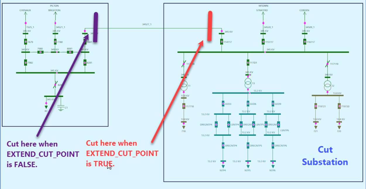
- INCLUDE_RADIAL_STATIONS: If TRUE, radial cut Substations will be fully included in the buffer zone. A radial Cut Substation is only connected to Substations inside the buffer zone. This is normally to rectify region-based CUT_DEFINITION. Generally, cutting radial Substations is unnecessary.
- REMOVE_INTERNAL: If TRUE, all of the modeling entities related to the Internal will be removed. In this case, Terminals of the boundary branches will be ready for stitching.
- REMOVE_SMALL_ISLANDS: If TRUE, small node-based islands will be removed from the buffer zone. These small islands could be inherited from source model or result from model cutting.
- RESET_CUT_STATION_REGION: If TRUE, the region/sub-regions of the Cut Substations will be reset to those of the corresponding connected Substations inside the buffer zone. This is to avoid dragging regions/sub-regions of the Cut Substations to the buffer zone. This setting is applicable only when EXTEND_CUT_POINT is TRUE.
Adding Equivalents
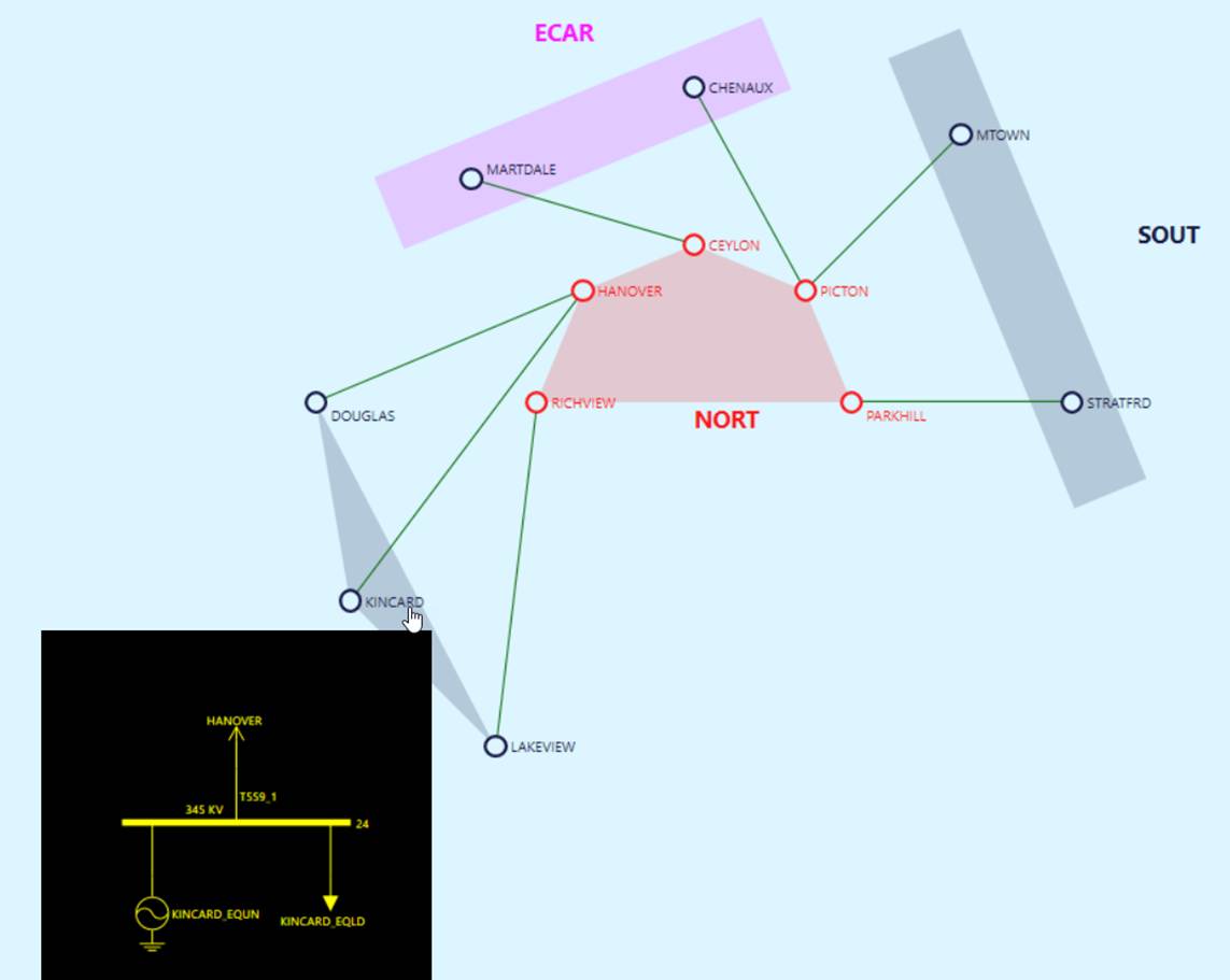
Equivalent injections can be optionally placed at the cut points in the form of load, generating unit, or EquivalentInjection . More specifically,
- ADD_EQ_LOAD: If TRUE, a specified type of load, i.e. EquivalentInjection, EnergyConsumer or its derived class, will be added for each cut point.
- LOAD_TEMPLATE: defining the class and properties of equivalent load in the form of ClassName/PropertyName1=PropertyValue1; PropertyName2=PropertyValue2… Meaningful only when ADD_EQ_LOAD is TRUE.
- ADD_EQ_UNIT: If TRUE, a generating unit (SynchronousMachine and GeneratingUnit) will be added for each cut point.
- UNIT_TEMPLATE: defining the class and properties of equivalent synchronous machine in the form of ClassName/PropertyName1=PropertyValue1; PropertyName2=PropertyValue2… Meaningful only when ADD_EQ_UNIT is TRUE.
- GEN_TEMPLATE: defining the class and properties of equivalent generating unit in the form of ClassName/PropertyName1=PropertyValue1; PropertyName2=PropertyValue2… Meaningful only when ADD_EQ_UNIT is TRUE.
- Depending how the buffer zone is cut, the equivalent injections will be added at cut Substations or Substations connecting to cut Substations.
Marking Points of Interests
Optionally (when MARK_POINT_OF_INTEREST is TRUE), points of interests (POIs), such as boundary objects, cut objects, and equivalent objects, can be marked as CIM extensions:
- boundary: if ‘true’, the object is a boundary Substation, ACLinSegment/SeriesCompensator, ConnectivityNode, or Terminal.
- cut: if ‘true’, the object is a cut Substation, ACLinSegment/SeriesCompensator, or ConnectivityNode.
- equivalent: if ‘true’, the object is an equivalent load, or generating unit.
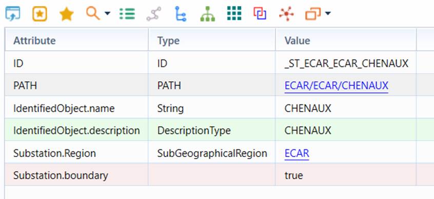
There are two purposes for marking POIs:
- Creating custom reports that display boundary/cut points.
- Supporting custom processes created in Python or C++ for integration/customization, for example stitching the buffer zone with the Internal. This is the primary use. With POI marking, the relevant objects of interest can be quickly identified.
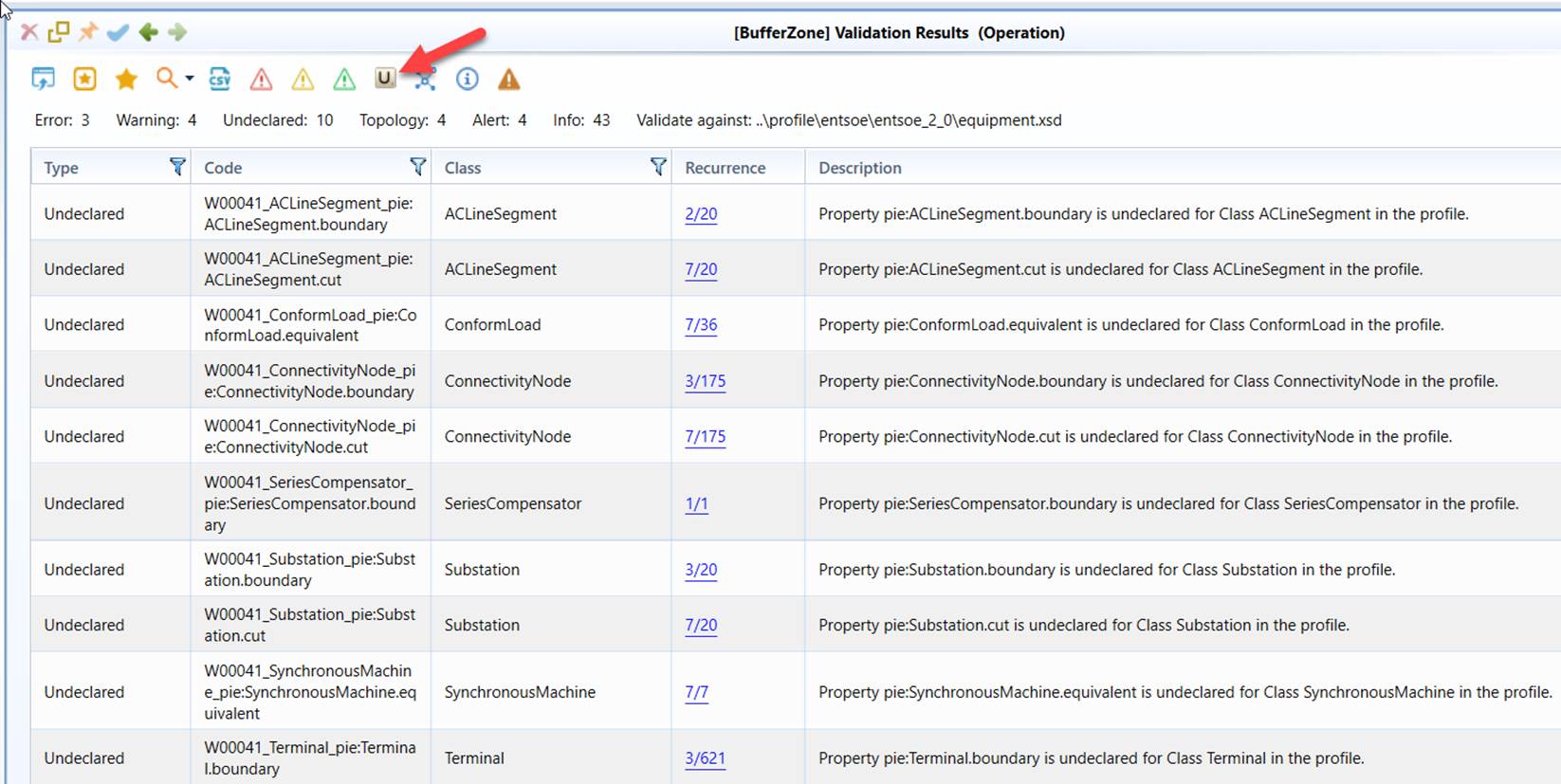
While creating custom reports is the formal way for displaying POIs, a quick way is to run model validation for the extracted sub-model. All of the marked POI objects will be reported as Undeclared objects, as illustrated below.
Summary of Configurations
The External Model Export process is completely controlled by a set of configuration settings defined in a CSV file. The CSV file is used because this is the format familiar to modeling engineers, even though it is not proper for defining structured settings. All of the configuration settings are defined as key/value pairs. As needed, conventions are used to declare some of the structured configuration settings. The following table summarizes all of the configuration settings.
| Key | Value (Example) | Description |
|---|---|---|
| MODEL_NAME | BufferZone | The name of the full model created for the extracted external sub-model. |
| BOUNDARY_DEFINITION | GeographicalRegion/Name: ECAR | Defining the boundary between internal and buffer zone. The boundary is defined by a set of (internal) boundary Substations and boundary branches. See user’s guide about how to declare BOUNDARY_DEFINITION. |
| CUT_DEFINITION | Substation/Name: COBDEN; BVILLE; | SubGeographicalRegion/Name: NORT | Defining how the retained portion of the external network ( referred to as buffer zone) shall be cut from rest of the external network. This is defined by a set of Substations that are connected to the buffer zone, but shall not be included in the buffer zone. These Substations are referred to as Cut Substations. See user’s guide about how to declare CUT_DEFINITION. |
| EXTEND_CUT_POINT | TRUE | If TRUE, the cut points will be extended to the side of the Cut Substations |
| MAX_DEPTH | 100 | Used to restrict the search within a certain depth. This setting can also be used to extract a buffer zone based on the neighborhood distance, for example, a buffer zone containing all of the Substations that are within distance of 5 branches. As a special notation, a value of 0 means infinity. |
| MAX_NUMB_OF_STATIONS | 10000 | Used to detect whether the search goes beyond the intended buffer zone. The search will be aborted if the number of the retained Substations is greater than MAX_NUMB_OF_STATIONS. This configuration shall be set to a number that is greater than the estimated number of Substations in the buffer zone. In this case, once MAX_NUMB_OF_STATIONS is reached, this normally means CUT_DEFINITION is either incomplete or incorrect. As a special notation, a value of 0 means infinity. |
| INCLUDE_RADIAL_STATIONS | TRUE | If TRUE, radial cut Substations will be fully included in the buffer zone. A radial Cut Substation is only connected to Substations inside the buffer zone. This is normally to rectify region-based CUT_DEFINITION. Generally, cutting radial Substations is unnecessary. |
| REMOVE_INTERNAL | FALSE | If TRUE, all of the modeling entities related to the Internal will be removed. In this case, Terminals of the boundary branches will be ready for stitching. |
| REMOVE_SMALL_ISLANDS | FALSE | If TRUE, small node-based islands will be removed from the buffer zone. These small islands could be inherited from source model or result from model cutting. |
| MAX_SMALL_ISLAND_NODES | 100 | Used to define small islands. Islands that have fewer than MAX_SMALL_ISLAND_NODES ConnectivityNodes will be treated as small islands. Meaningful only when REMOVE_SMALL_ISLANDS is TRUE. |
| RESET_CUT_STATION_REGION | FALSE | If TRUE, the region/sub-regions of the Cut Substations will be reset to those of the corresponding connected Substations inside the buffer zone. This is to avoid dragging regions/sub-regions of the Cut Substations to the buffer zone. This setting is applicable only when EXTEND_CUT_POINT is TRUE. |
| ADD_EQ_LOAD | TRUE | If TRUE, a specified type of load, i.e. EquivalentInjection, EnergyConsumer or its derived class, will be added for each cut point. |
| LOAD_TEMPLATE | ConformLoad/EnergyConsumer.pfixed=0; EnergyConsumer.qfixed=0 | Defining the class and properties of equivalent load in the form of ClassName/PropertyName1=PropertyValue1; PropertyName2=PropertyValue2… applicable only when ADD_EQ_LOAD is TRUE. |
| LOAD_NAME | EQLD | Default name of the equivalent loads, applicable only when ADD_EQ_LOAD is TRUE. |
| ADD_EQ_UNIT | TRUE | If TRUE, a generating unit (SynchronousMachine and GeneratingUnit) will be added for each cut point. |
| UNIT_TEMPLATE | SynchronousMachine/RotatingMachine.ratedS =0; SynchronousMachine.minQ=0; SynchronousMachine.maxQ=0; SynchronousMachine.type= SynchronousMachineType.generator; SynchronousMachine.operatingMode =SynchronousMachineOperatingMode.generator | Defining the class and properties of equivalent synchronous machine in the form of ClassName/PropertyName1=PropertyValue1; PropertyName2=PropertyValue2… applicable only when ADD_EQ_UNIT is TRUE. |
| GEN_TEMPLATE | GeneratingUnit/GeneratingUnit.minOperatingP=0; GeneratingUnit.maxOperatingP=0 | Defining the class and properties of equivalent generating unit in the form of ClassName/PropertyName1=PropertyValue1; PropertyName2=PropertyValue2… applicable only when ADD_EQ_UNIT is TRUE. |
| UNIT_NAME | EQUN | Default name of the equivalent generating unit, applicable only when ADD_EQ_UNIT is TRUE. |
| USE_PATH_AS_ID | TRUE | If TRUE, object PATH will be used to generate rdf:IDs for equivalent objects. rdf:IDs generated from PATH are relatively persistent. Applicable only when ADD_EQ_LOAD or ADD_EQ_UNIT is TRUE. |
| PREFIX_STATION_NAME | TRUE | If TRUE, Substation name will be used as prefix of the names of the equivalent objects. Applicable only when ADD_EQ_LOAD or ADD_EQ_UNIT is TRUE. |
| APPENDIX_NUMBER | FALSE | If TRUE, number will be used as appendix of the names of the equivalent objects. Applicable only when ADD_EQ_LOAD or ADD_EQ_UNIT is TRUE. |
| MARK_POINT_OF_INTEREST | TRUE | If TRUE, points of interests (POIs), such as boundary objects, cut objects, and equivalent objects, will be marked as CIM extensions. With POI marking, the relevant objects of interest can be quickly identified, thus facilitating custom processes. |