Setting up Graphical Modeling Environment
This article describes setup of the environment essential for graphical modeling, including prerequisites, settings, and tips necessary for performing the graphical modeling tasks.
Enabling of Graphical Model Editing
The graphical model editing function will be automatically enabled if the following conditions are satisfied:
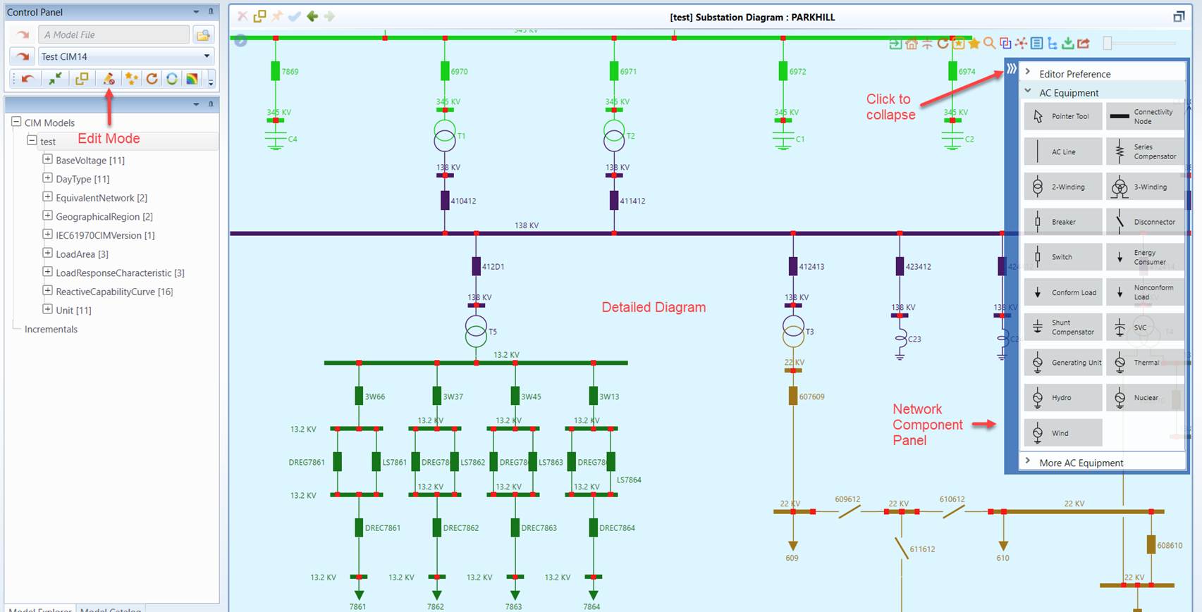
- The Tool is in the Edit Mode, i.e. with the Edit flag checked as illustrated.
- A detailed Substation or Line/Equipment Diagram is displayed. The diagram could be auto-generated or previously saved. The graphical model editing requires the detailed node/breaker model to be used. Users will not be able to use this function if the edited model is a pure bus/branch model, i.e. with TopologicalNode , but no ConnectivityNode.
Once the graphical editing function is available, Component Panel will be available, enabling users to pick up the network component and add it to the diagram. This panel is collapsible. The graphical modeling entity in Component Panel is auto-generated from the CIM profile that governs the loaded model. Therefore, if different versions of CIM models are loaded, you may find the contents of Component Panel varied. This panel shall contain all types of the network components, including ConnectivityNode and every ConductingEquipment declared in the supported version of CIM.
Display Options
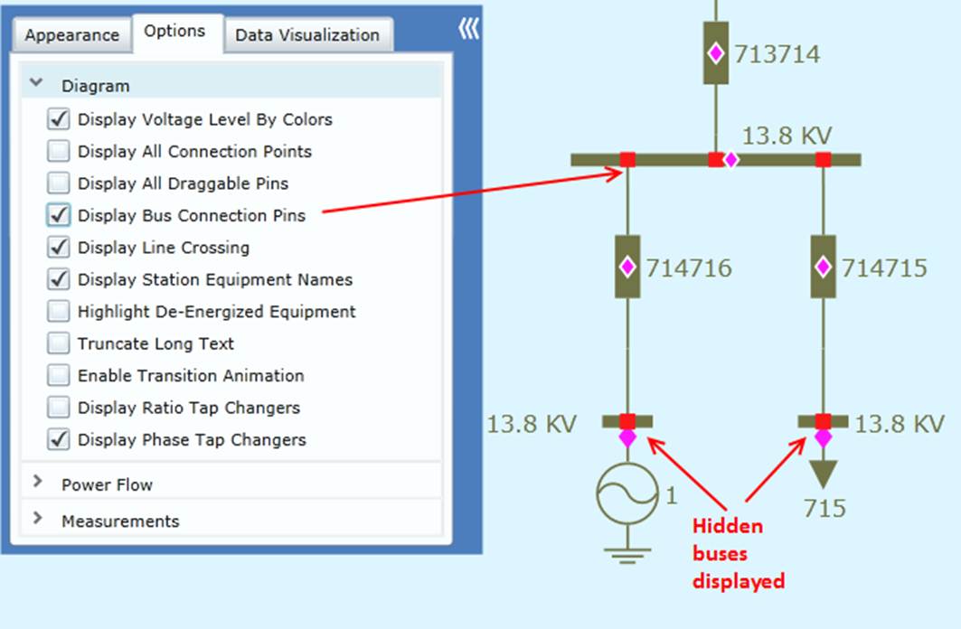
Once entering the graphical modeling mode, users will see the targeted Substation Diagram is refreshed with all of the hidden buses displayed. Each ConnectivityNode is explicitly rendered as a bus in the diagram. This is a designed behavior. Users don’t have to explicitly change the display options for this. However, in non-edit mode, there is a new option for user to hide/display hidden buses. On the other hand, users are strongly recommended to set the default option to explicitly “Display Bus connection Pins and “Display Node Names” since pins and nodes are essential for connecting or reconnecting the equipment.
During the Edit mode, diagram property pop-ups intentionally are disabled to avoid distractions.
Entity Adding Mode
After selecting a modeling entity from the component panel, users enter the entity-adding mode where users can add the new network components to the diagram, and thus adding CIM objects to the underlying data models. As illustrated in the following screenshot, the cursor will then carry an image, indicating the type of new modeling entity to be added. Users can always roll back to the default mode by selecting the “Pointer Tool” in the Component Panel, pressing the Esc key, or selecting “Cancel Editor Action” in the context menu triggered by right-mouse click. Users can also change the selected modeling entity by clicking the new modeling entity in the Component Panel. When users clone or copy a selected network component in the diagram, the tool will also enter the Entity-Adding mode automatically.
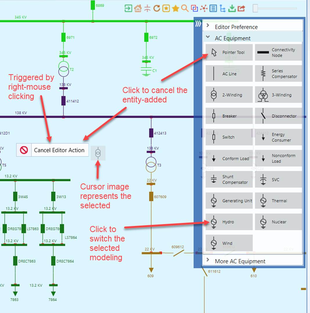
Diagram Re-layout
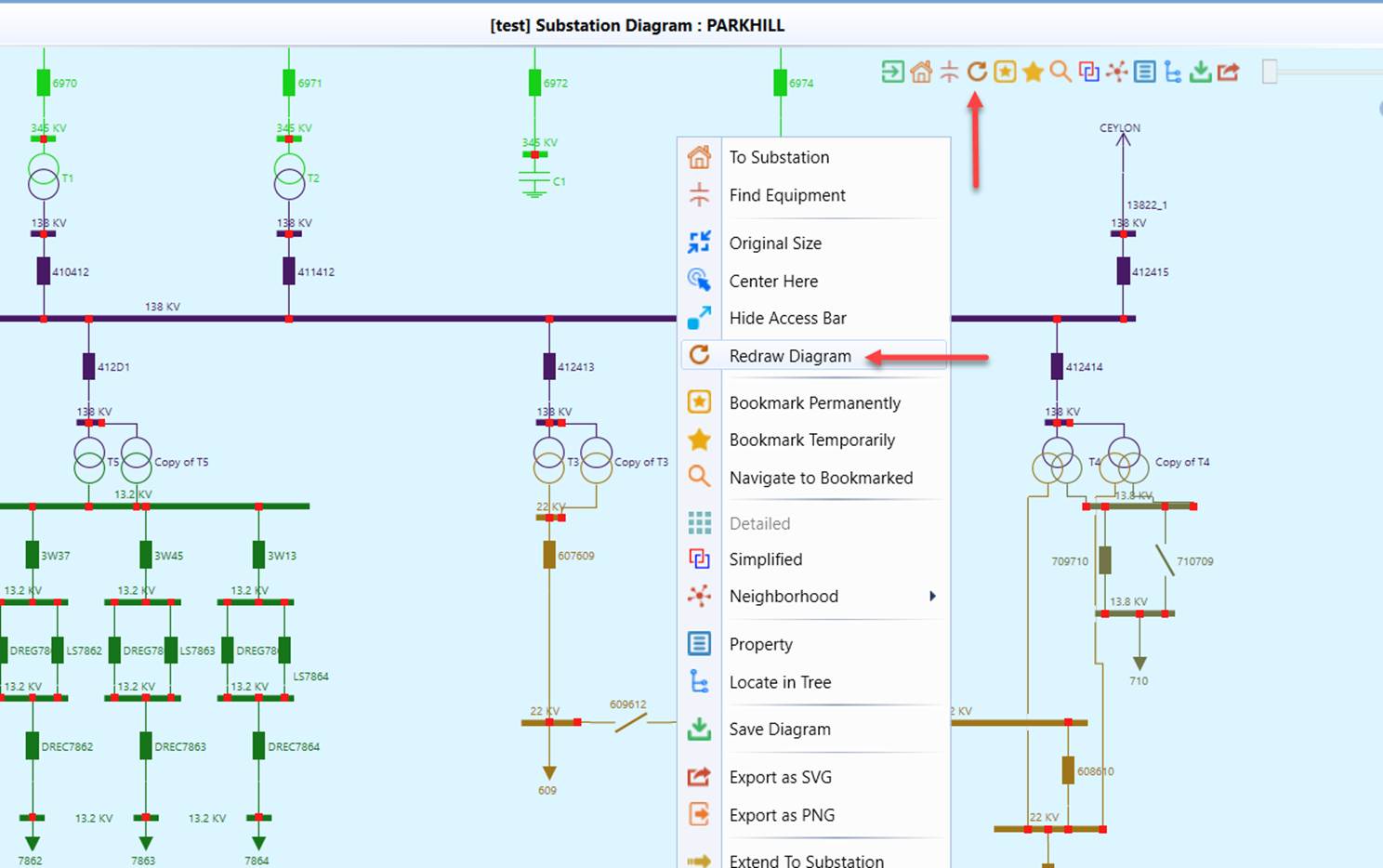
During graphical model editing, the originally auto-generated Substation Diagrams are likely changed, with some network components added, deleted or reconnected. The resulting diagram layout can look messy with overlapping components and labels. This is expected, since the original Substation Diagram layout is generated based on the network connectivity of the original model. While users can adjust the diagram manually to fit the model changes, a more convenient way is to re-layout the diagram automatically based on the modified model. The following screenshot illustrates how to re-layout.
The following screenshot is the re-drawn diagram reflecting the new model changes. As shown in the screenshot, the new layout is optimized, reflecting the model changes committed.
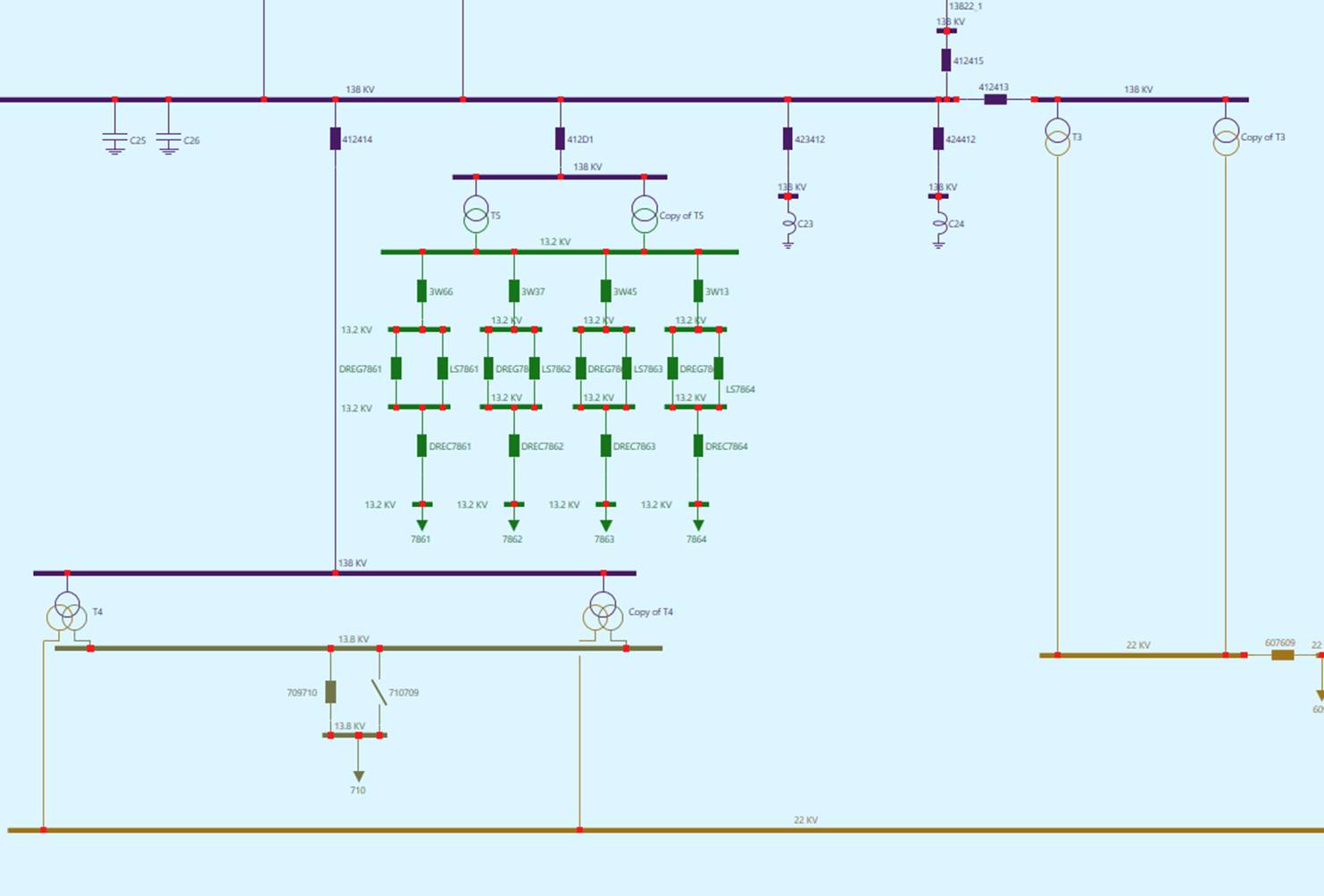
The diagram re-layout feature is particularly useful for modeling in a dual substation diagram introduced below.
Dual-Substation
Typically the graphical modeling activities are performed within a single Substation. But in some cases, users want to add and connect a new equipment between two Substations or clone/copy a selected network component from other Substations. In such cases, two Substations shall be displayed side-by-side with/without equipment connected between them. This is called Dual-Substation display. It can be invoked through context menu as illustrated. Once invoked, user will be prompted to select an existing Substation from the wizard.
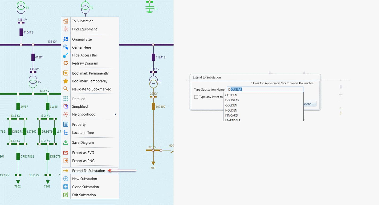
Once an existing substation is selected, a dual substation diagram will be displayed, showing two substations side by side. Each substation is displayed within a rectangular boundary. Modeling activities can be performed for either substation in a dual substation diagram, but the activities must be performed within the boundary of the targeted substations or between two substations. For example, users are not allowed to drop a ConnectivityNode outside the boundary of a Substation. Users can also switch the extended substation to a new substation or go back to the original single substation display through context menu as illustrated.
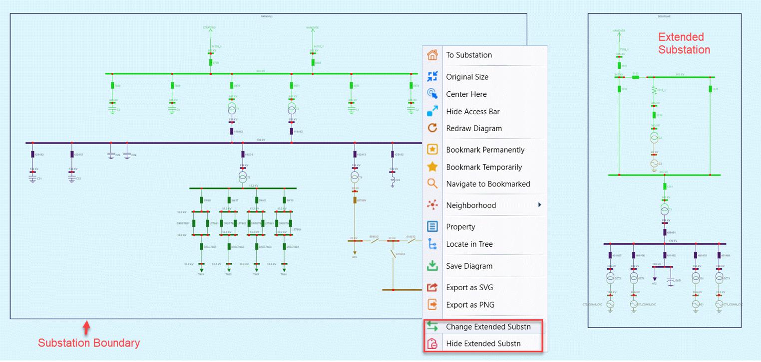
The dual substation can also be invoked through a ConductingEquipment (typically lines) that connects two Substations. The resulting dual substation diagram is identical to cross-station equipment diagram.
Commitment vs. Undoing
It is important to note that the graphical model editor commits all model changes instantly to the underlying model. This can be observed by watching the navigation tree update. There is no separate saving process involved in graphical model editor unlike in object editor where users need explicitly save the model changes. This is a designed behavior following the principle of what-you-see-is-what-you-get.
Undoing is not supported in this version of the Tool.
Diagram Update
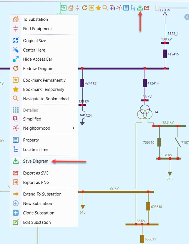
Users can graphically edit the model from a saved Substation Diagram or Line/Equipment Diagram. But the diagram must be explicitly saved to reflect the committed model changes. Otherwise, users will be informed of these changes every time the saved diagram is called. The Tool doesn’t automatically update the saved diagrams.
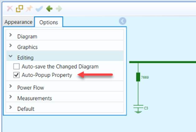
Property Auto-Popup
After users add a new modeling entity either from the Component Panel or via copy-and-paste or cloning, they typically want to edit the newly-added modeling entity. While property editing can be achieved by double-clicking the added modeling entity or via a context menu associated with the added modeling entity, users can configure an option to automatically pop-up the property sheet for editing whenever a new modeling entity is added either from the Component Panel or via copy-and-paste or cloning. This option is called “Auto-Popup Property” and in the Editor Preference option group, as shown below. When selected, the Tool will automatically popup the property sheet for users to edit any newly-added modeling entity. This feature will prompt users always to edit the added modeling entity at the first time, a good modeling habitat. However, the Tool doesn’t enforce this rule. By default, this option is disabled. Like other graphical options, this option is persistent and stored locally as user profile. So it is mainly a one-time setting.