Run Power Flow
Power flow can be executed for any loaded models conforming to CGMES 2.4.15/CGMES 3.0 or CIM 16/CIM 17 and containing the required model parts/contents. Various input and output options are provided in support of different use cases.
Hands-On (Required)
Take Hands-on Lab 1-4 from Power Flow Tutorial.
Run Power Flow
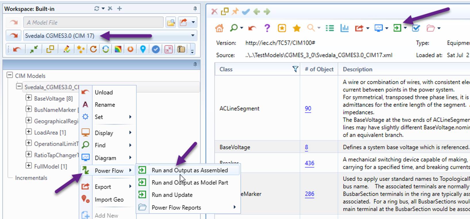
Power flow can be invoked either from the context menu associated with model tree node or by clicking the command icon the model Summary, as illustrated below.
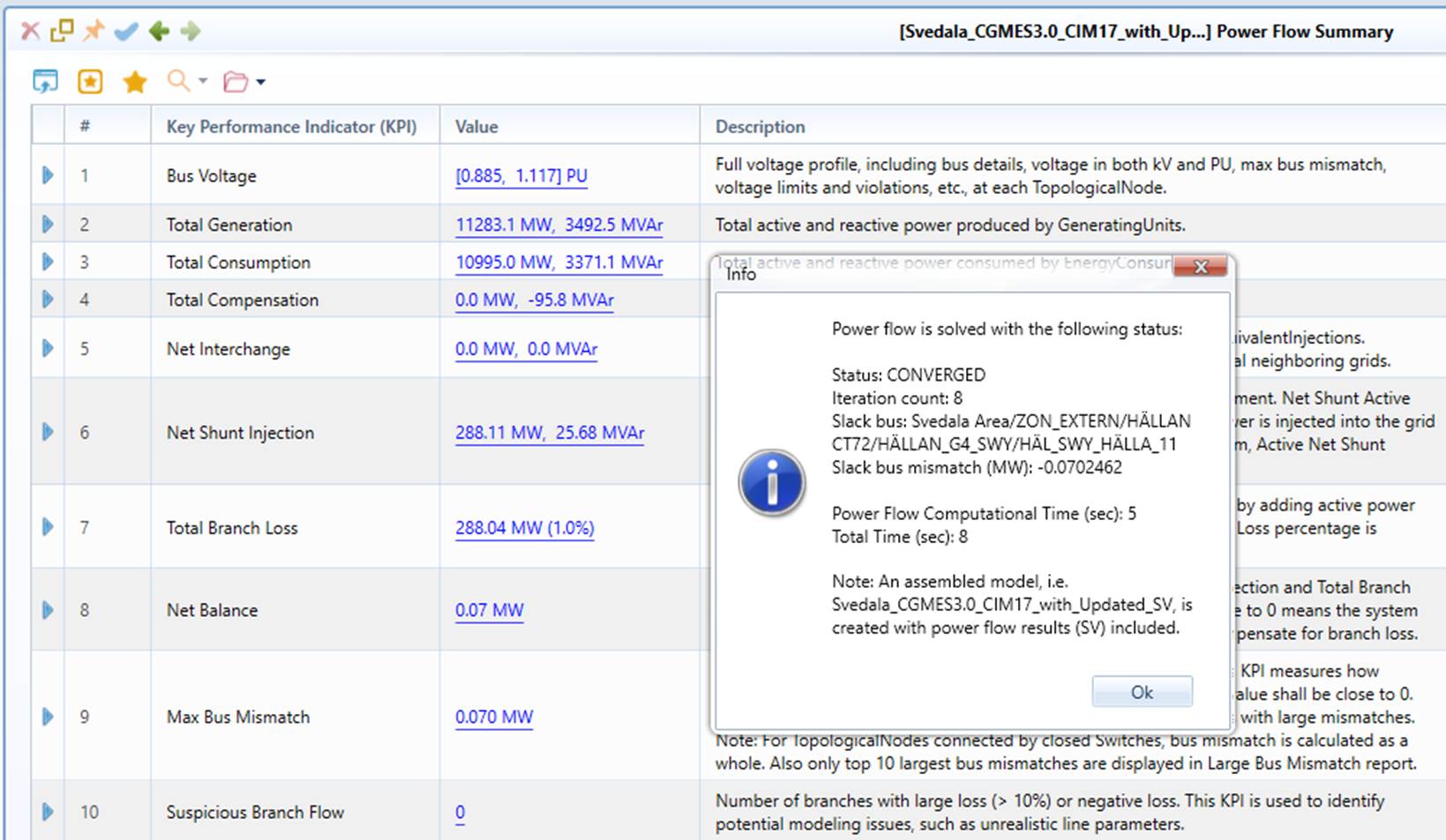
Once the power flow execution is completed, a status message pops up. If the power flow converges, the Power Flow Summary report will be displayed if the output is an assembled model.
Note
The Power Flow context menu or command icon is only available for the qualified loaded models, i.e. CGMES 2.4.15/CGMES 3.0 or CIM 16/CIM 17 models with the required model contents, as defined in the Input Option.
Additionally, power flow can also be executed from diagrams in an interactive model.
Note
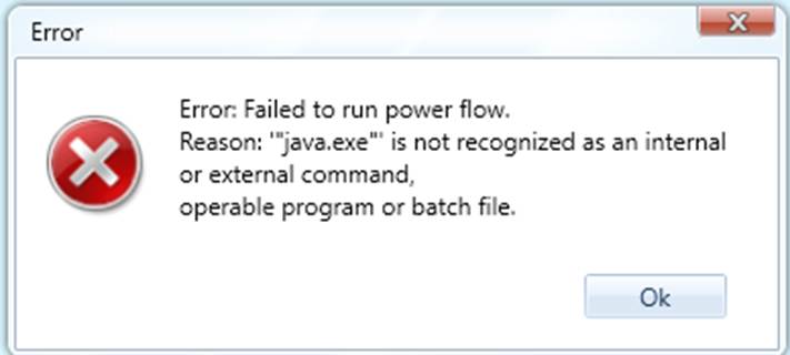
If you see the following message, it means that Java is not installed. The power flow engine, i.e. PowSyBl, is a java application. It requires Java 11 or a later version to be installed. Please Set Up Power Flow Environment first.
Input Options
The power flow function is currently available for
- CGMES 2.4.15 (CIM 16) and CGMES 3.0 (CIM 17)
- Node/Breaker, Bus/Branch, and a mixture of them
- Individual Grid Model (IGM) and Common Grid Model (CGM)
The required input could be one of the following:
- Model Parts, including
- Equipment (EQ): equipment connection, line/transformer parameters...
- Steady State Hypothesis (SSH): switch status, load/generator MW/MVAr injection...
- Topology (TP): topology analysis results (bus-based) required for bus/branch, and optional for node/breaker
- Assembled of required model parts
Once the required models are loaded, power flow can be invoked from
- Model Parts:
- Equipment (EQ) or Boundary Equipment (EQ_BD) for Individual Grid Model (IGM), See Hands-on Lab 2
- Boundary Equipment (EQ_BD) for Common Grid Model (CGM) , See Hands-on Lab 3
- Assembled: See Hands-on Lab 1 and 4
Note:
- If the input is model parts, all of the required model parts, including the dependent boundary set (i.e. EQ_BD/EQ_TP), must be loaded into the workspace, each with model dependency and profile URIs properly specified in meta-data (i.e. the FullModel instance).
- For node/breaker models, the Topology (TP) model part/content is not required. If the TP model part/content is not provided, the Tool will populate the TP model part/content. However, if the TP model part/content is provided for IGM, the Tool will use it instead of populating TP (assuming no model changes are detected.)
- For node/breaker models, if the loaded model is edited in the Tool, the original TP model part/content, if provided, will be discarded. The Tool will derive new TP model part/content for power flow calculation. This applies for any changes made in any model parts, even the introduced model changes have no impact on power flow calculation.
Output Options
When executing power flow, users must choose what types of output shall be produced, as illustrated below:
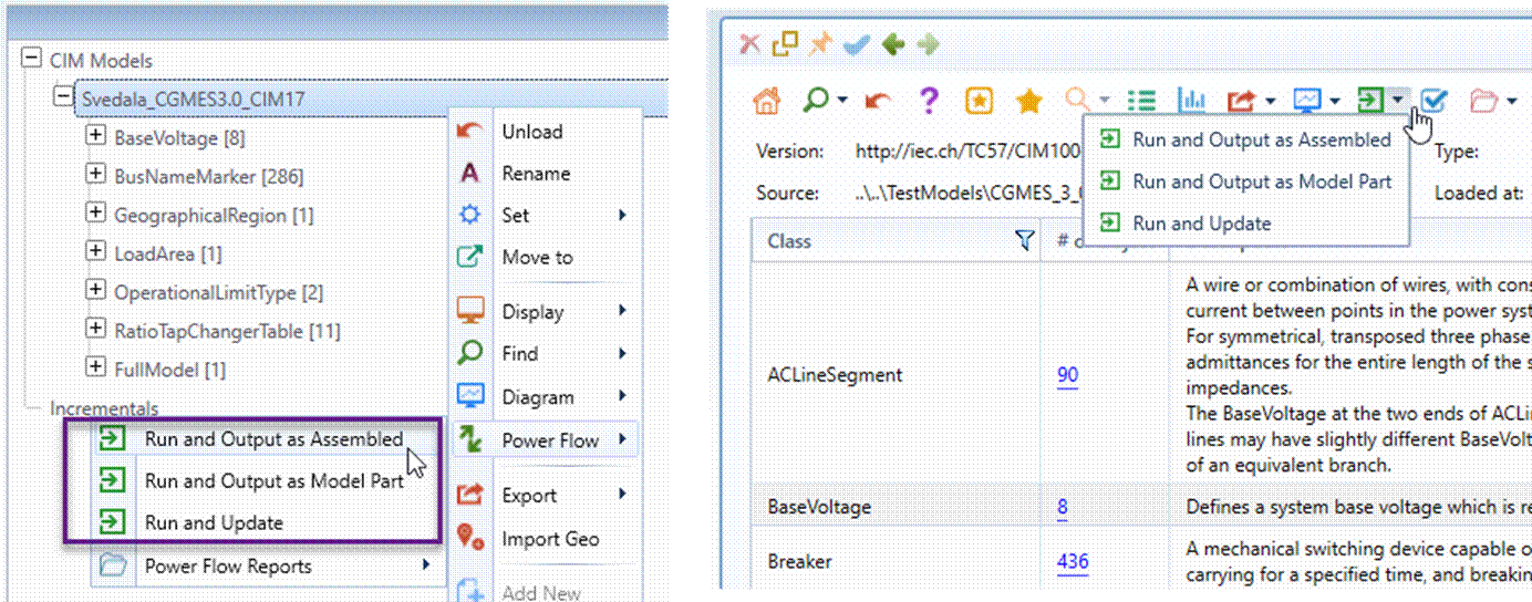
The support output options include:
- Run and Output as Assembled: The output is a separate assembled model including all of the input model parts/contents and calculated power flow results (i.e. State Variable or SV). This is the mostly used output option, since only assemble model is ready for power flow reporting and visualization.
- Run and Output as Model Parts: The output is separate model parts generated by the power flow function. This option is only used to generate power-flow-result-only data set for archiving or submittal. Depending on the input, the following model parts can be generated:
- Sate Variable (SV): bus voltage, branch flow, etc. This is always generated under any circumstances if power flow converges.
- Topology (TP): only if TP is not provided for node/breaker or any model changes are detected.
- Run and Update: This option is only available when the input is an assembled model. It is normally used for supporting Interactive Power Flow. The output is the input model itself with the above model parts/contents added or replaced.
Debugging
Power flow doesn’t solve? You may review the log, change the configuration, or check the known issues, etc., to start a debugging process.